Dot Product
Contents
Overview[edit]
The Dot product node takes the Main Input and Input 2 vectors and outputs the dot product of the two vectors, which is a scalar value. The dot product is the cosine of the angle between the two vectors multiplied by the lengths of the two vectors.
The dot product is useful because it can tell us about the relationship between two vectors. If the dot product equals 0 then the two vectors are at 90º to each other (perpendicular). If the dot product is greater than 0 then two vectors are pointing roughly in the same direction. If the dot product is less than 0 then the two vectors are pointing away from each other.
The dot product is even more useful when the two vectors are unit vectors. In that case the dot product is the cosine of the angle between the two vectors. You can also get the cosine of the angles between non-unit vectors using the following formula:
cosine = Dot product( vector 1, vector 2 ) ÷ ( Length( vector 1 ) x Length( vector 2 ) )
The cosine value will range between 1 and -1. If the two vectors are pointing in the same direction the value will be 1. If they're at right angles to each other the value will be 0. If one vector is pointing in exactly the opposite direction to the other vector (i.e. 180º to the other vector) the value will be -1.
To find the actual angle between the vectors in degrees you can do this:
angle in degrees = Radians to degrees( Arccos( cosine ) )
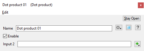
This node has just the one setting, which lets you choose a node for Input 2.
Settings:
- Name: This setting allows you to apply a descriptive name to the node, which can be helpful when using multiple Dot Product nodes in a project.
- Enable: When checked, the node is active and the dot product multiplication operation will take place. When unchecked the values assigned to its Main Input, if any, are passed through, otherwise a value of 0 is passed through.
- Input 2: A dot product operation takes place between the component values from the shader or function nodes assigned to this setting and those from the Main Input. When nothing is assigned, the Main Input values, if any, are passed through. If the Main Input is unassigned, the output from the node is 0.
Fun with Dot Product[edit]
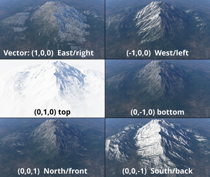
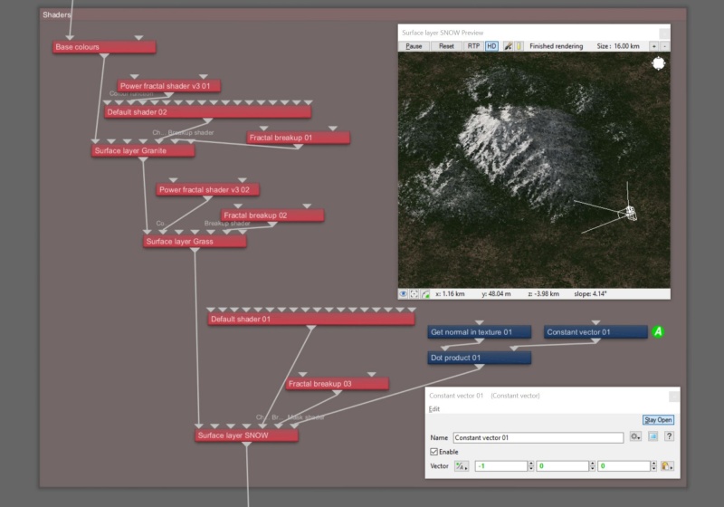
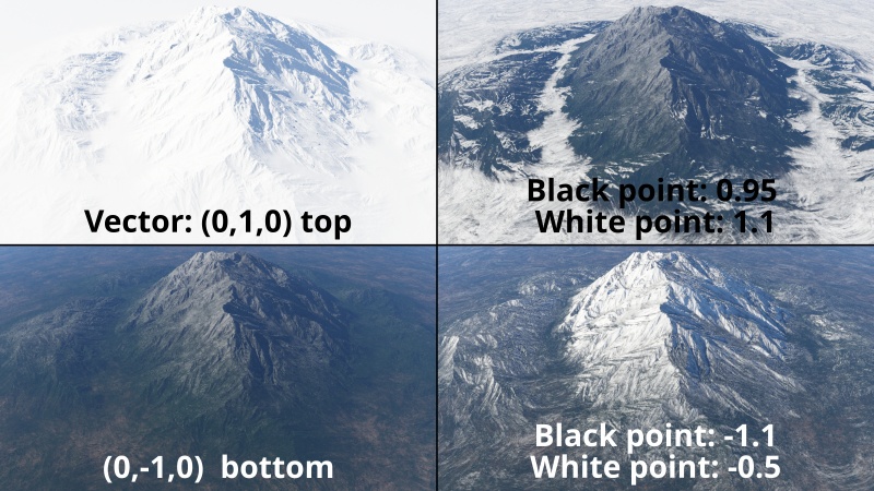
Using the Dot Product node, you can create masks based on a heading or direction. For example, you can create a mask in order to apply snow to a particular side of a mountain, as shown in the following example images.
The Get normal in texture node provides the Main Input of the Dot Product node with the normal vector for a given sample point on the terrain. You specify the direction that you want the snow effect to occur by entering values in the XYZ input fields of a Constant vector node which is assigned to the Input 2 parameter of the Dot Product node. For example, a value of 1 in the X axis field would limit the snow to the East, or right side of the mountain.
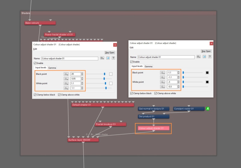
You can further manipulate the mask created by Dot Product node by connecting its output to a Colour Adjust node, then adjusting the Black point and White point parameters. This provides a method for controlling the opacity of the mask.
A scalar is a single number. 1, 200.45, -45, -0.2 are all examples of scalar values.
A vector is a set of three scalars, normally representing X, Y and Z coordinates. It also commonly represents rotation, where the values are pitch, heading and bank.
A single object or device in the node network which generates or modifies data and may accept input data or create output data or both, depending on its function. Nodes usually have their own settings which control the data they create or how they modify data passing through them. Nodes are connected together in a network to perform work in a network-based user interface. In Terragen 2 nodes are connected together to describe a scene.
A shader is a program or set of instructions used in 3D computer graphics to determine the final surface properties of an object or image. This can include arbitrarily complex descriptions of light absorption and diffusion, texture mapping, reflection and refraction, shadowing, surface displacement and post-processing effects. In Terragen 2 shaders are used to construct and modify almost every element of a scene.
A sample refers to a value or set of values at a point in time and/or space. The defining point of a sample is that it is a chosen value out of a continuous signal. In Terragen 2 it is usually a mathematical (procedural) function that is being sampled.
A parameter is an individual setting in a node parameter view which controls some aspect of the node.
