Camera
Overview[edit]
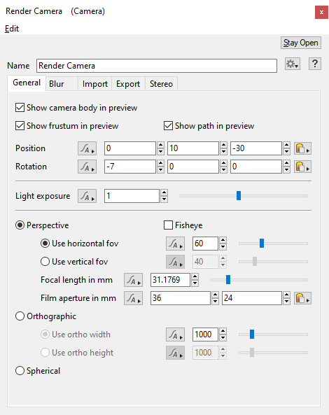
The Camera node is one of the fundamental nodes in Terragen. The Camera gives you the view into your scene. It's a bit like a real camera - you use it to take a snapshot of the virtual landscape. The Camera node provides several controls similar to real-world physical cameras, including Light Exposure, Position and Rotation, as well as Field Of View, or FOV, which is similar to the "zoom" function of a real camera. To use a camera for a final render it needs to be connected to the Camera input of the Render node you're using for the render. You can have multiple cameras and you can attach multiple Render nodes to a single camera if you want them to share the same view in the scene, but you can only have 1 Camera node per Render node. Cameras have other uses aside from rendering scenes as well. You can create a camera and connect it to a Distance Shader to control where another shader appears. You could also create a camera and connect it to an Image map shader to project an image texture onto your scene.
Settings
- Name: This setting allows you to apply a descriptive name to the node, which can be helpful when using multiple Camera nodes in a project.
General Tab[edit]
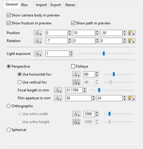
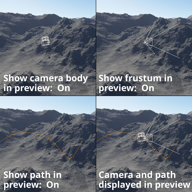
- Show camera body in preview: When checked, the camera body will be visible in the 3D Preview. When unchecked, it is hidden from view.
- Show frustum in preview: When checked, the camera’s frustum will be visible in the 3D Preview. When unchecked, it is hidden from view.
- Show path in preview: When checked, the camera’s path will be visible in the 3D Preview. In order for the path to be visible, there must be at least one keyframe for the camera’s position or rotation.
- Position: This setting is used to translate and position the camera in the 3D scene. The Animation button directly to the right of the label gives you complete control over the position keyframes. You can set or remove keyframes for each individual channel or all of them, as well as import or delete entire animations, or open the Animation panel for this item.
-
The current position values may be copied and pasted by clicking on the coordinate copy/paste button to the right of the XYZ numerical input fields.
- Rotation: This setting is used to rotate the camera in the 3D scene. The Animation button directly to the right of the label gives you complete control over the rotation keyframes. You can set or remove keyframes for each individual channel or all of them, as well as import or delete entire animations, or open the Animation panel for this item. The current rotation values may be copied and pasted by clicking on the coordinate copy/paste button to the right of the Pitch, Heading, and Bank numerical input fields.
- Light exposure: This setting adjusts the camera’s exposure, simulating the response to light a real camera might have. Lowering the value darkens the image, much like stopping down the lens aperture, from f/2 to f/4 for instance. Increasing the value brightens up the image, allowing more light to reach the film. The following Light exposure values correspond to Terragen’s exposure slider tool, EV, at the bottom left of the 3D Preview.
| Light exposure | Exposure value |
|---|---|
| 0.0 | -Infinity |
| 0.125 | -3.0 |
| 0.25 | -2.0 |
| 0.5 | -1.0 |
| 1.0 | 0.0 |
| 2.0 | 1.0 |
| 4.0 | 2.0 |
| 8.0 | 3.0 |
- Perspective: When checked, the camera uses perspective projection. This is the default setting.
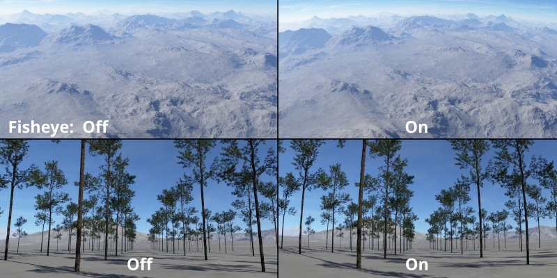
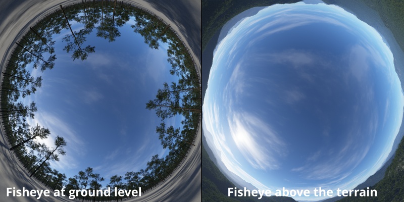
- Fisheye: When checked, the camera views the scene as if a fisheye lens was attached to it. More specifically this is an "equidistant" or "linear scaled" fisheye projection. This can be used to render full hemispheres if you set the field of view to 180 degrees and render to a square image.
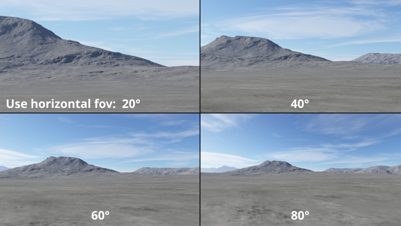
- Use horizontal fov: When checked, this setting controls the camera’s horizontal field of view. The slider to the right can be used to set the field of view angle in degrees. Adjusting this setting also has an effect on the Vertical field of view and Focal length in mm settings.
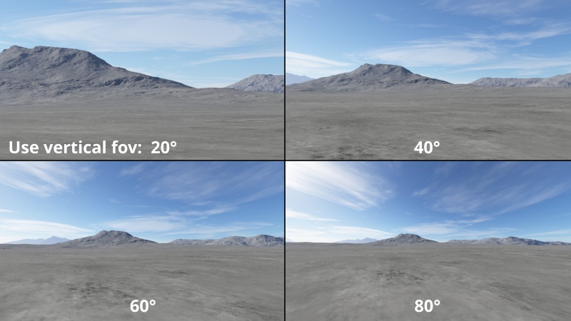
- Use vertical fov: When checked, this setting controls the camera’s vertical field of view. The slider to the right can be used to set the field of view angle in degrees. Adjusting this setting also has an effect on the Horizontal fov and Focal length in mm settings.
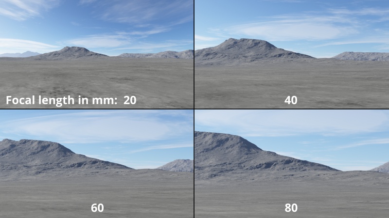
- Focal length in mm: This setting controls the focal length of the virtual lens used for the camera and is the equivalent to the focal length of a real camera lens.
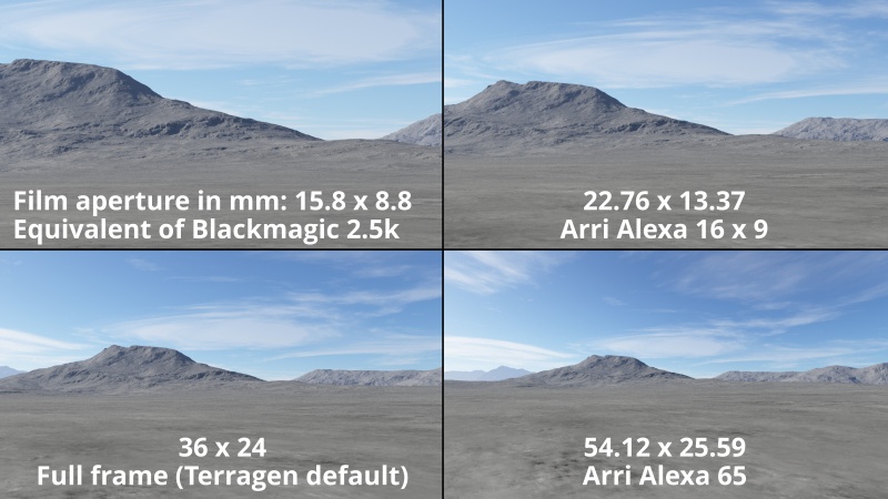
- Film aperture in mm: This setting simulates the size of film, or the sensor, in a real camera. The default settings match the width and height of 35mm film.
- Orthographic: When checked, the camera uses an orthographic projection. This removes the effect of perspective and can be useful for top down images, for example.
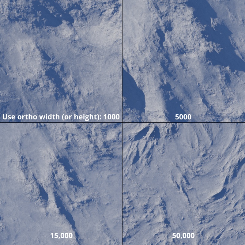
- Use ortho width: This sets the width in metres of the area captured by the orthographic camera. For example, if this is set to 500 then an area 500m wide and centred around the camera position will be rendered. The height of the area captured will depend on the aspect ratio of the rendered image, as set by the Render node used.
- Use ortho height: This sets the height in metres of the area captured by the orthographic camera. For example, if this is set to 500 then an area 500m tall and centred around the camera position will be rendered. The width of the area captured will depend on the aspect ratio of the rendered image, as set by the Render node used.
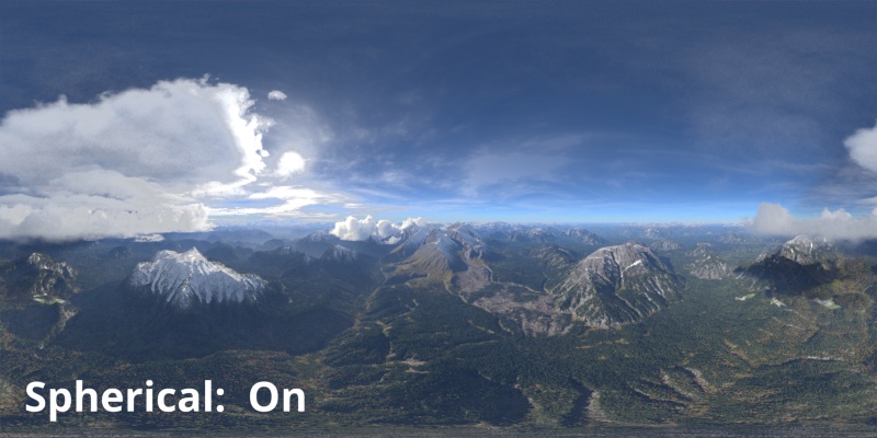
- Spherical: This setting allows you to produce a “Lat/long” or spherical render with a 360 degree field of view horizontally, 180 degrees vertically. The rotation of the camera matters. Typically you would set the camera’s rotation parameters to 0,0,0 when using the spherical projection. The camera’s position determines the point at which the scene is viewed from.
Blur Tab[edit]
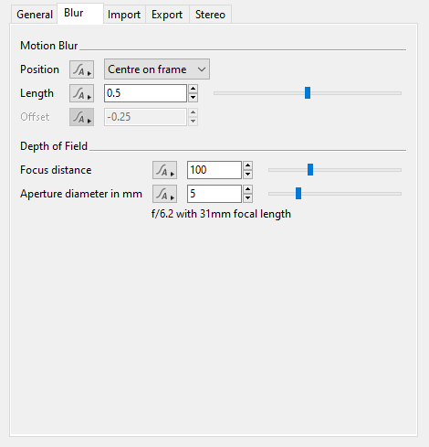
The settings on this tab provide control over motion blur and depth of field. These features are only available in licensed versions of Terragen. Currently, Terragen does not support object motion blur, only camera motion blur.
To render motion blur in Terragen versions 2.5 to 4.4, motion blur must be enabled on the render node, not just the camera. However, turning off motion blur on the renderer is not quite the same as turning it off on the camera. Even with motion blur turned off on the renderer, it still uses the shutter window to calculate motion vectors, if these are output via Terragen’s Render Layers, and always renders an image that is centred in the shutter window so that the rendered image can be properly motion blurred in post. The image might not use the exact camera values for the frame. To ensure that it does, set motion blur length to 0 and shutter offset to 0. This behaviour has changed in v4.5. In v4.5 and above you can simply turn off motion blur on the render node to get exact-frame values.
- Position: This popup menu has four options to let you choose the point in time at which the motion blur starts.
-
Start on frame: When selected, the virtual camera shutter opens at the start of the frame and remains open for the length of time specified by the Length setting.
Centre on frame: When selected, the virtual camera shutter opens before the frame and closes after the frame, equally centered around the frame for the length of time specified by the Length setting..
End on frame: When selected, the virtual camera shutter closes on the frame, having remained open for the length of time specified by the Length setting.
Custom: Selecting this option exposes the Offset parameter, giving you complete control over the motion blur effect.
- Length: This is the total length of time, in frames, during which the camera's shutter is open, affecting how much motion blur is visible when the camera is moving. If motion blur length is 0 there will be no motion blur, regardless of how fast the camera is moving. If motion blur length is 0.5, the default, the shutter will be open for exactly half the amount of time that the camera moves between one frame and the next. This is the most popular choice. It produces motion blur similar to a 180-degree shutter in a film camera, or a shutter of 1/48 second in a 24 FPS video. If motion blur length is 1, the shutter will be open for the full duration of time that the camera moves between one frame and the next. This is not possible in a real camera, but if it were it would be equivalent to a 360-degree shutter, or a shutter of 1/24 second in a 24 FPS video. Other values can be chosen, even those outside the range 0 to 1, but it is very unusual to go outside this range in animations.
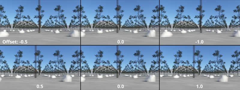
- Offset: This value offsets the time, in frames, at which the motion blur shutter opens and closes. A shutter offset of 0, the default, causes the shutter to open exactly on the frame number and close at frame + motion blur length. If, instead, you set the offset to -0.5 times the motion blur length (e.g. -0.25 shutter offset with the default motion blur length of 0.5), the motion blur will be centred on the current frame. Choosing the correct shutter offset may be important if Terragen renders need to be composited with tracked footage or output from other renderers.
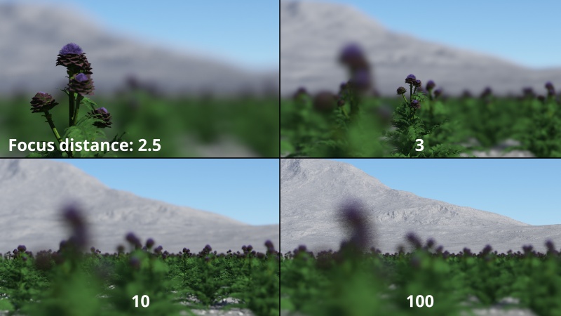
- Focus distance: This sets the distance from the camera that will be in focus. The depth of field, that is the area in focus in front of and behind this value, is determined by the camera’s Focal length in mm setting and the Aperture diameter in mm setting.
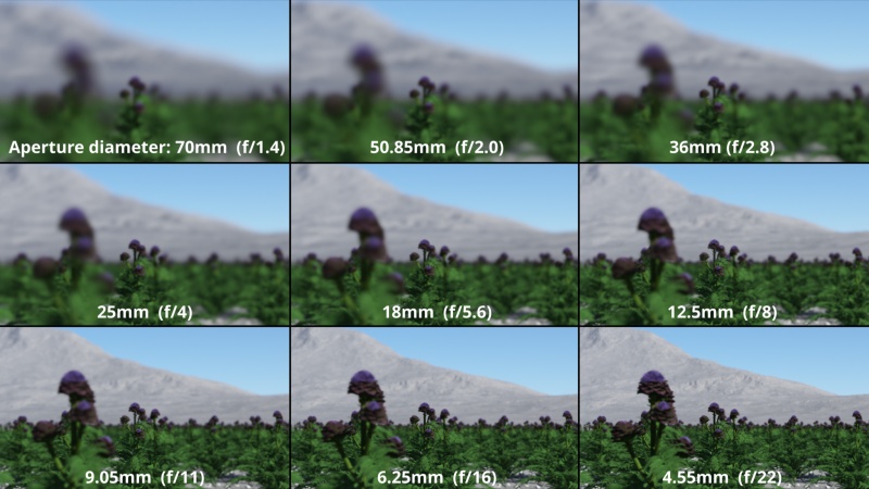
- Aperture diameter in mm: This setting simulates a real world camera aperture. In a real camera the size of the aperture is one of the controls for how much light reaches the film plane. The higher this setting’s value, the larger the opening to allow light in, which results in a greater depth of field, or more area in focus around the Focus distance value. In the example image below, the Focal length of the camera is set to 100mm and the focal distance to 2.5 metres.
- F-stop & focal length: This read only setting displays the corresponding f-stop and current focal length of the camera. It updates as the Depth of field settings are adjusted.
Import Tab[edit]
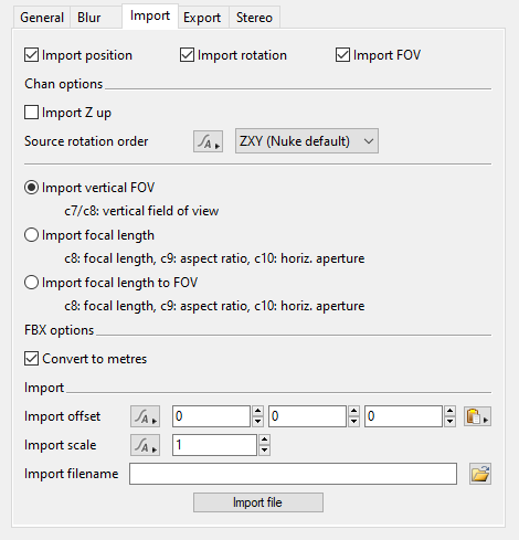
The Import tab of the Camera node allows you to import Nuke or Houdini .chan files, Maya .mov files or FBX files to set camera params. It can import multiple frames from a file for animation. The .chan field of view related params have hint text showing how they interpret the file data. For example if you check the Import vertical FOV radio button then either channel 7 (c7) of a Houdini .chan file or channel 8 (c8) of a Nuke .chan file will be read as a vertical field of view setting. You read more about importing .chan/.mov files here. For more information about importing FBX files please see the FBX Reference.
- Import position: When checked, the position data from the .chan/.mov or FBX file will be imported.
- Import rotation: When checked, the rotation data from the .chan/.mov or FBX file will be imported.
- Import FOV: When checked, the field of view (FOV) data from the .chan/.mov or FBX file will be imported.
.Chan options
- Import Z up: When checked, it is assumed the data in the file uses Z up for its coordinates. Terragen will convert that to its Y up coordinate system.
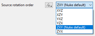
- Source rotation order: This popup menu contains six options which allow you to match the rotation order from the source file.
- Import vertical FOV: When checked, Terragen will read the 7th or 8th value of the .chan file, depending on the file format, as the vertical field of view (FOV).
- Import focal length: When checked, the .chan file must have 10 values per line. Terragen reads the 8th value as focal length, the 9th as aspect ratio, and the 10th as horizontal aperture.
- Import focal length to FOV: When checked, the .chan file must have 10 values per line. Terragen reads the 8th value as focal length, the 9th as aspect ratio, and the 10th as horizontal aperture. Terragen then converts this information to field of view.
.FBX options
- Convert to metres: When checked, the imported units are converted to metres. In Terragen 1 unit = 1 metre. This setting is checked by default.
Import options
- Import offset: This setting allows you to offset the positions imported from the file. For example, you might want the positions imported from the file to be moved 10 metres in the X direction. To do that, simply enter 10 for the X coordinate and click the Import file button.
- Import scale: This setting allows you to scale the values imported from the file.
- Import filename: This setting specifies the file to be imported. Clicking on the Open file button to the right will open a file dialogue window and prompt you for a new file to import. If you choose not to import it immediately you can click the Import File button to perform the import. If you're importing an FBX file the FBX Import: Camera dialog will open to let you choose which camera from the file you want to import, along with some other options.
- Import file: Click this button to import the file specified in the Import filename setting.
Export Tab[edit]
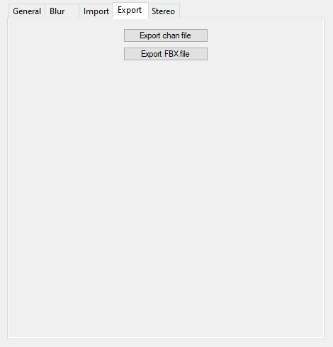
The buttons on this tab allow you to export camera data, including position, rotation and FOV data as a .chan file or FBX file. Camera animation is exported if you have the Animation module.
Chan files are exported as Nuke .chan files. Animation is baked, so there is a line in the file for every frame in the animation. There are 8 values per line, ordered like this:
- Frame number
-
X
-
Y
-
Z
-
Rotate X
-
Rotate Y
-
Rotate Z
-
Vertical field-of-view
Each value is separated by a space.
When you export an FBX file the following settings are used:
- Animation is baked, that is a keyframe is set for every frame of animation.
- The frame rate is set to 24 fps.
- Units are converted to centimetres.
- The export format is FBX v7.3.
If you need more control over these settings you can export the entire scene (perhaps choosing to only export cameras) using the "Export FBX Scene" item in the File menu. For more information about exporting FBX files please see the FBX Reference.
- Export chan file: Click this button to export the camera data to a .chan file.
- Export FBX file: Click this button to export the camera data to a FBX file.
Stereo Tab[edit]
The settings on this tab allow you to set up and control options for Stereo output (e.g. for VR, stereo VFX production, etc.).
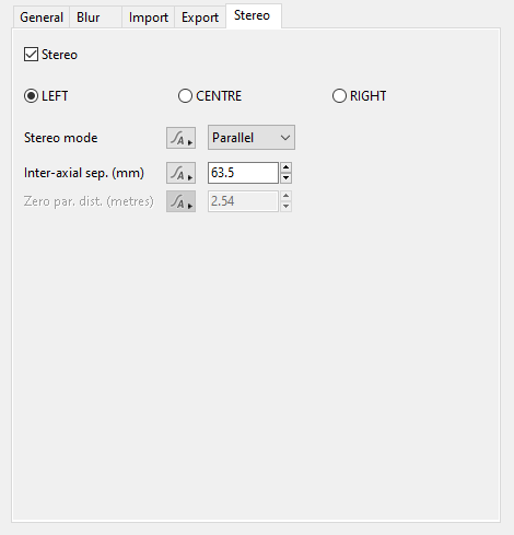
- Stereo: When checked, the settings below become active.
- LEFT: When checked, the camera is internally shifted to the left by half the distance of the Inter-axial separation value. For example, if the camera’s position was keyframed at the origin (0,0,0) and the Inter-axial value was the equivalent of 1 metre, then the stereo left camera would render the frame from (-0.5,0,0).
- CENTRE: When checked, the camera is not shifted to the left or right, but remains at its keyframed position.
- RIGHT: When checked, the camera is internally shifted to the right by half the distance of the Inter-axial separation value. For example, if the camera’s position was keyframed at the origin (0,0,0) and the Inter-axial value was the equivalent of 1 metre, then the stereo right camera would render the frame from (-0,0,0.5).
- Stereo Mode: This popup menu has two options which allow you to choose the manner in which the stereoscopic renders are created.
Parallel: When selected, the left and right cameras remain parallel to each other and do not converge.
Off axis: When selected, the left and right cameras remain parallel to each other, but converge at the Zero parallax distance setting point.
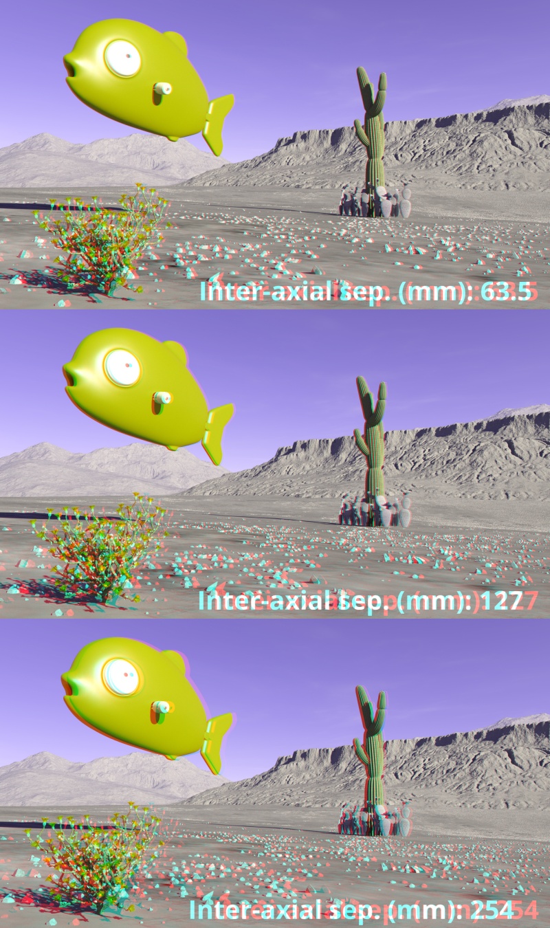
- Inter-axial sep. (mm.): This value represents the distance or separation between the two cameras used to create the stereoscopic effect. The default setting of 63.5 mm, or 2.5 inches, represents the average distance between a human being’s left and right eye. In the example images below, the left and right camera renders have been combined into an anaglyph image. To see the image in 3D use a pair of red/cyan 3D glasses.
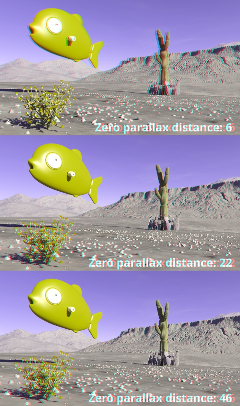
- Zero par. dist. (metres): This value sets the distance between the camera and the zero parallax plane, the point in the scene at which the terrain features or 3D objects have no parallax. In the example images below, the left and right camera renders have been combined into an anaglyph image. To see the image in 3D use a pair of red/cyan 3D glasses.
A single object or device in the node network which generates or modifies data and may accept input data or create output data or both, depending on its function. Nodes usually have their own settings which control the data they create or how they modify data passing through them. Nodes are connected together in a network to perform work in a network-based user interface. In Terragen 2 nodes are connected together to describe a scene.
A shader is a program or set of instructions used in 3D computer graphics to determine the final surface properties of an object or image. This can include arbitrarily complex descriptions of light absorption and diffusion, texture mapping, reflection and refraction, shadowing, surface displacement and post-processing effects. In Terragen 2 shaders are used to construct and modify almost every element of a scene.
A parameter is an individual setting in a node parameter view which controls some aspect of the node.
