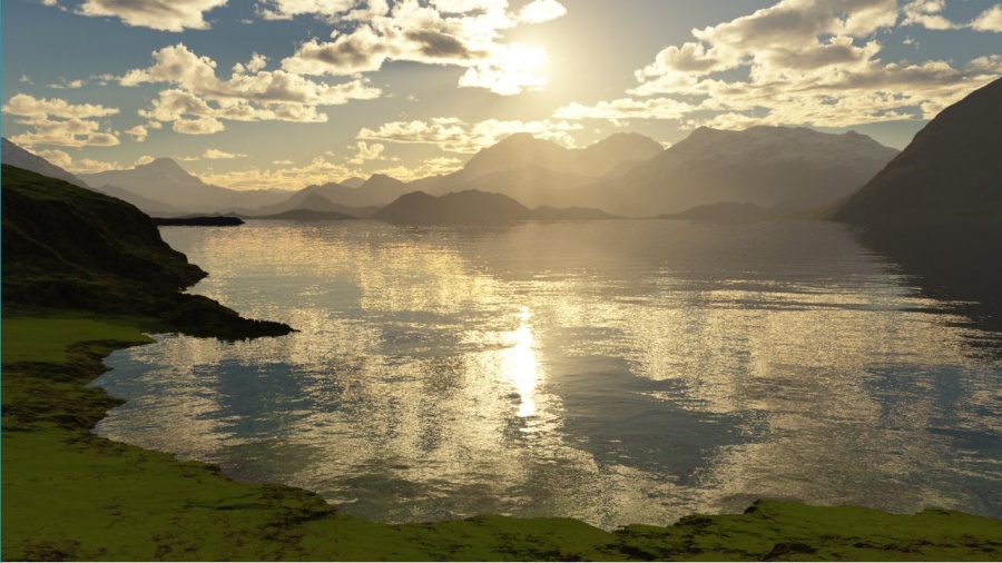
Tutorial 2: Adding a Lake
Contents
Introduction[edit]
This tutorial will walk you through adding a lake to a scene in Terragen. Conveniently, lakes have their own dedicated object in Terragen, so we’ll just be adding a lake object and tweaking some of its properties.
This tutorial is designed as a follow-up to “Creating Your First Scene.” If you’re new to Terragen and haven’t yet completed that tutorial, it’s recommended that you do so now, as it covers a lot of fundamentals that this tutorial will assume you know.
Before You Get Started[edit]
If You Completed “Creating Your First Scene”[edit]
If you finished the “Creating Your First Scene” tutorial, start by loading that project. It’ll be more interesting to work with a scene that already has textured terrain and dramatic lighting. However, there are a couple of things you should adjust to make it easier to work with this tutorial.
Also, you may want to save your project as a new name before we get started, just in case anything goes wrong.
Disabling the “Easy cloud 01” Layer Node[edit]
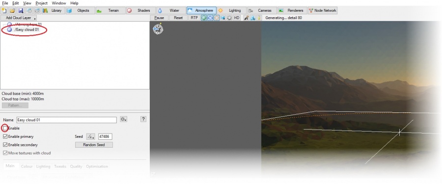
Clouds take a lot of resources to render in both the 3D Preview and when creating a full render. (You probably noticed this after you added them in “Creating Your First Scene.”) We don’t need to see them as we’re working on this tutorial, so let’s turn them off for now. Select the Atmosphere layout.
In the Atmosphere layout, select your cloud layer node (it should be “Easy cloud 01”, unless you decided to rename it). In the node properties pane, uncheck Enable. This will turn the cloud layer off for now. You can easily turn it back on by re-enabling it.
Creating a Speedy Renderer[edit]
Remember how at the end of the “Creating Your First Scene” tutorial, we modified the renderer settings to create a higher-quality image? That’s great for creating a final render, but it’s too slow for creating snapshot renders as we work. So let’s add a second renderer that will give us quicker output. Select the Renderers layout.
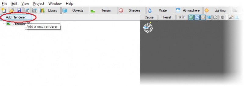
Click the Add Renderer button. A new renderer, “Renderer 02”, will be added.
The renderer will be created with the default settings, which are good for creating quick renders while we’re working. There are just a few things we'll want to change.
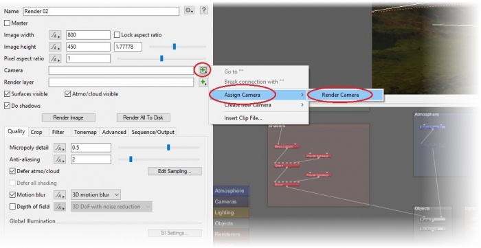
First off, this renderer needs to have a camera assigned to it, or it won’t be able to create a render. Click the Add button on the Camera line, and select Assign Camera > Render Camera (the Render Camera is the only camera we currently have, so it will be the only camera on the list). The Render Camera is now assigned to this renderer. Note that cameras can be assigned to multiple renderers, so this won’t change the fact that our other renderer is using the same camera.
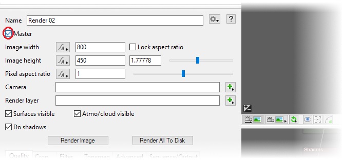
We want this to be the default renderer whenever we load this project, so select Master.
Now that we have two renderers, we should give them descriptive names. Let’s go with “High-quality Renderer” for the first (the one currently named “Render 01”), and “Quick Renderer” for the second (the one currently named “Render 02”).
When you render the image via the Open Render View workflow or by pressing Ctrl+R/Cmd+R, Terragen will use whichever renderer you last selected on this layout. If the renderer we just renamed to “Quick Renderer” is not currently selected, click it to select it now.
Raising the Sunlight 01 Elevation[edit]
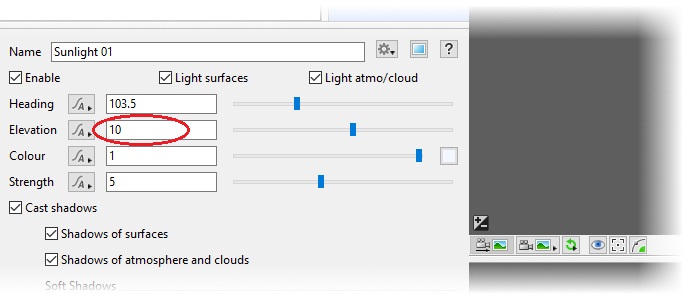
We chose a very low-angle sun in the previous tutorial to create a nice, dramatic sunset. However, it won’t give us quite enough light to see everything that’s happening in this and subsequent tutorials. Let’s raise it to 10. Navigate to the Lighting layout and select “Sunlight 01” from the Node List. In the Node Properties pane, change the Elevation to 10. This should still give us interesting shadows and light, but it's now high enough that we can see the features of our scene more clearly.
If You Didn’t Complete “Creating Your First Scene”[edit]
If you don’t need the “Creating Your First Scene” tutorial and you’re just interested in learning about water, that’s fine. Ideally you already have a scene with the terrain and lighting you want, and you’re adding water to that.
Adding a Lake[edit]
Lakes are added as objects in Terragen. With the lake object, you have the ability to create a body of water anywhere you choose. You can modify properties such as wave characteristics, wind effects, color, and clarity. Let's take a look at how to use the lake object in more detail.
Select the Water layout. This is where you add a “Lake” object.
Lakes normally appear in valleys, so make sure the camera is positioned somewhere where you’re looking down into a valley, preferably one surrounded by some dramatic mountains.
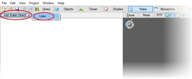
To add a lake object, click Add Water Object > Lake.
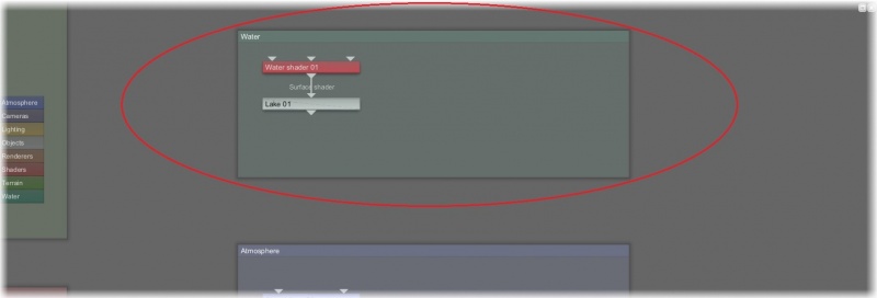
You have now added a lake at the 0, 0, 0 coordinate origin. This also did something interesting in the Node Network. Let’s pause and take a look at that now. We want to center on the Water node group and zoom in. Click anywhere in the Node Network pane to select it. If you can’t see the Water group, hold Alt, then click and drag to move around the node pane until you can see it. Mouse over the Water group and rotate the mouse wheel to zoom in on it.
You can see that this added both a lake object node (“Lake 01”) and an attached surface shader node (“Water shader 01”). This surface shader is what makes the lake object look like water. We won't be looking further at the Node Network in this tutorial, but it's good to start getting some awareness of it.
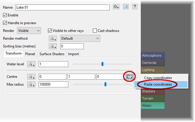
Let's focus back on the 3D Preview pane. You’ll probably at least see the blue wireframe of the lake, if not the lake itself. The lake was added at the 0, 0, 0 coordinate origin, which might be pretty far from what you’re looking at in the 3D Preview. To position the lake more in the area where you want it, move the mouse in the 3D Preview pane to a location that looks roughly like where you’d like the lake to be centered. Right-click, and select Copy Coordinates. In the Transform tab of the node properties, click the “Copy/paste coordinates” button on the Centre line and select “Paste coordinates”.
This will set the center of the lake to the coordinates you just copied. Now you should see the center of the lake and the blue wireframe in full detail.
Before we fine-tune the location of the lake, let’s adjust its size. The “Max radius” is a bit excessive for our purposes at its default value of 100000 meters. Take that down to 10000. You may not notice a difference, as the visible part of the lake is also constrained by the height of the terrain around it (in other words, most of that extra visible area is below the surface), but it’s good to keep the “Max radius” to a figure that’s close to the lake size we want.
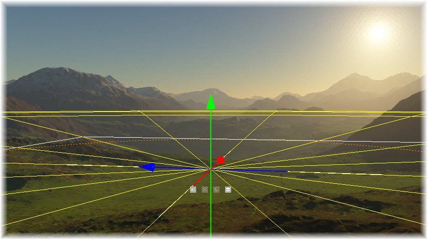
Now let’s fine-tune the location of the lake a bit. There are two ways to do this. The first is to adjust the Centre values, which are the XYZ coordinates of the lake (with the Y axis being the same as the “Water level” value; adjusting one value will automatically adjust the other to match). The second is to drag it into position in the 3D Preview pane. To do this, click the wireframe for the lake object in the 3D Preview pane. You will see the lines turn yellow, and three directional arrows will appear.
You can drag the arrows to move the lake object as follows:
- Green Arrow: Adjust the object on the Y axis (i.e. the height).
- Red Arrow: Adjust the object on the X axis.
- Blue Arrow: Adjust the object on the Z axis.
You can also drag the center of all 3 arrows to adjust all 3 values at once. Play with the location of the lake until you’re satisfied with its position.
| Note: The “Water level” and Y axis of the lake are measured from the base surface of the planet. So at 1 meter (the default value), the lake will probably be below surface of the mountainous terrain we created in the previous tutorial. I found that 600 meters was the right height for my scene, but yours may be quite different. |
Now let’s get nice and close to the shore so we can do a quick render and see how the water looks. As you move the camera around, note that the vertical height (Vheight) displays at the bottom of the 3D Preview pane. This number shows your height above the current terrain. Use this number to get close to the ground without going through. You should be close enough that you’ll be able to clearly see waves and texture in the water. Once you have the perfect spot picked out, don’t forget to copy the view to the current render camera.
| Note: The Vheight is measured from the surface of the terrain; it does not take the lake object into account. So if you are above the lake, the Vheight doesn’t show how far you are above the lake, but rather how far you are above the terrain that’s beneath the lake. |
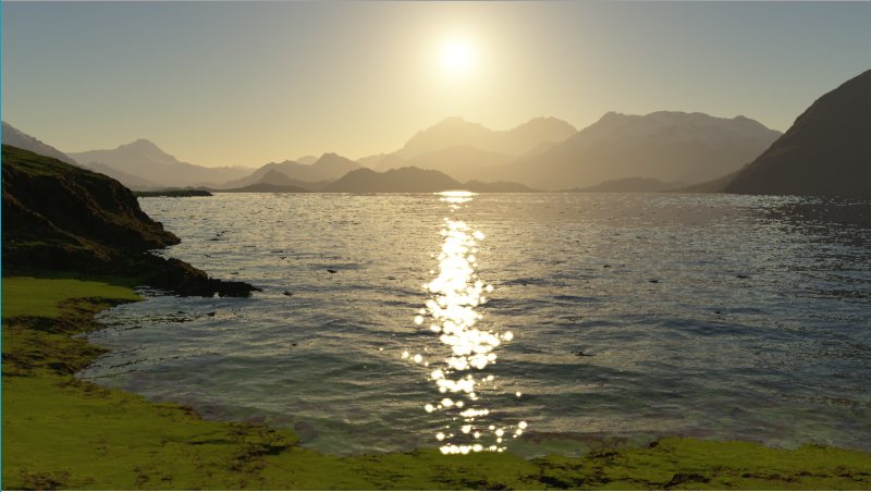
Try a render and see how it looks.
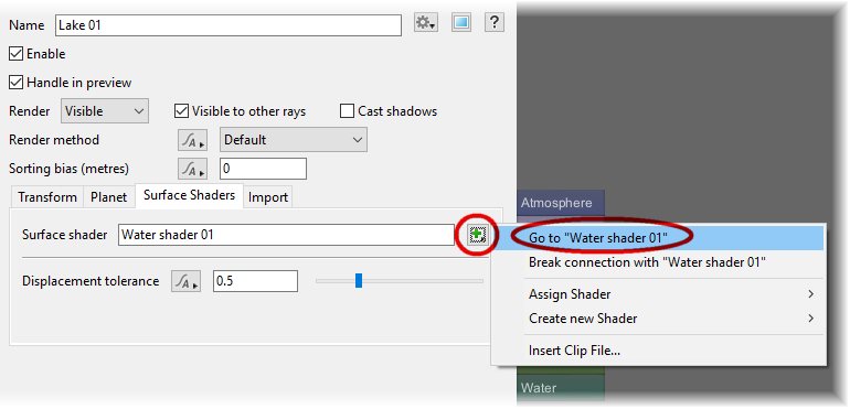
You can control the appearance of the water surface itself in the water shader settings. Let's take a look there now and tweak some of the settings. In the Node Properties pane, select the Surface Shaders tab. Click the box to the right on the “Surface shader” line and select “Go to “Water shader 01””.
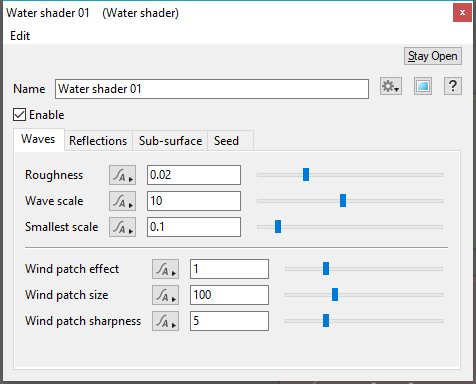
This will open the settings for the shader.
The Waves tab should be selected by default. Let’s look at a few of the settings here. Roughness controls the general roughness of the water surface. “Wave scale” is the average wave size. These two settings have the biggest impact on the look of our waves. The defaults create a fairly turbulent surface—accurate for what you’d see on a day with a good breeze. Let’s try something calmer, though. Set the Roughness to 0.003 and “Wave scale” to 15. Now try a render and see how it looks.
As you can see, there are a number of other options in the water shader’s properties. Their effects can be subtle, so this tutorial won’t explicitly instruct you to change any of their values. If you’d like to explore them a bit, refer to the online help for the node.
Once you’re happy with how your lake is looking, re-enable your cloud layer, switch to the high-quality renderer, and create a final render.
| Note: Not sure how to switch to the high-quality renderer? Remember that when you render the image either via the Open Render View workflow or by pressing Ctrl+R/Cmd+R, Terragen will use whichever renderer you last selected on the Renderers layout. So switch to the Renderers layout, select High-quality Renderer, and then render the scene. |
You’ve completed this tutorial! There’s more to water in Terragen than just lakes, though. You’re probably wondering about rivers and streams. Terragen allows you to use masking to create rivers and other more defined water features. You can even change the shape of the waves with custom displacement functions. These techniques will be covered in future tutorials.
Be sure to save your work before you exit!
A shader is a program or set of instructions used in 3D computer graphics to determine the final surface properties of an object or image. This can include arbitrarily complex descriptions of light absorption and diffusion, texture mapping, reflection and refraction, shadowing, surface displacement and post-processing effects. In Terragen 2 shaders are used to construct and modify almost every element of a scene.
A single object or device in the node network which generates or modifies data and may accept input data or create output data or both, depending on its function. Nodes usually have their own settings which control the data they create or how they modify data passing through them. Nodes are connected together in a network to perform work in a network-based user interface. In Terragen 2 nodes are connected together to describe a scene.
Literally, to change the position of something. In graphics terminology to displace a surface is to modify its geometric (3D) structure using reference data of some kind. For example, a grayscale image might be taken as input, with black areas indicating no displacement of the surface, and white indicating maximum displacement. In Terragen 2 displacement is used to create all terrain by taking heightfield or procedural data as input and using it to displace the normally flat sphere of the planet.
