Texturing with Surface Layers
Overview[edit]
A Surface Layer is a special node that contains many built in features, including the ability to apply colour, luminosity or displacements, as well as to mask the terrain based on altitude and slope constraints. Surface Layers can exist in Parent / Child relationships, which can help to both organize a project and further constrain an effect to a specific area. It also has a test parameter which can be used to visualize exactly where the effects are taking place on the terrain.
Set up[edit]
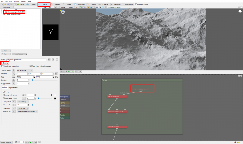
Let’s begin exploring how to use Surface Layers by first disabling the Simple shape shader that flattens the terrain in the default Terragen project. Click on the “Terrain” button below the Main Menu, then expand the Fractal terrain node in the Node list to reveal the Simple shape shader node and select it. Uncheck the “Enable” checkbox to disable the node and give us a mountainous terrain to work with..
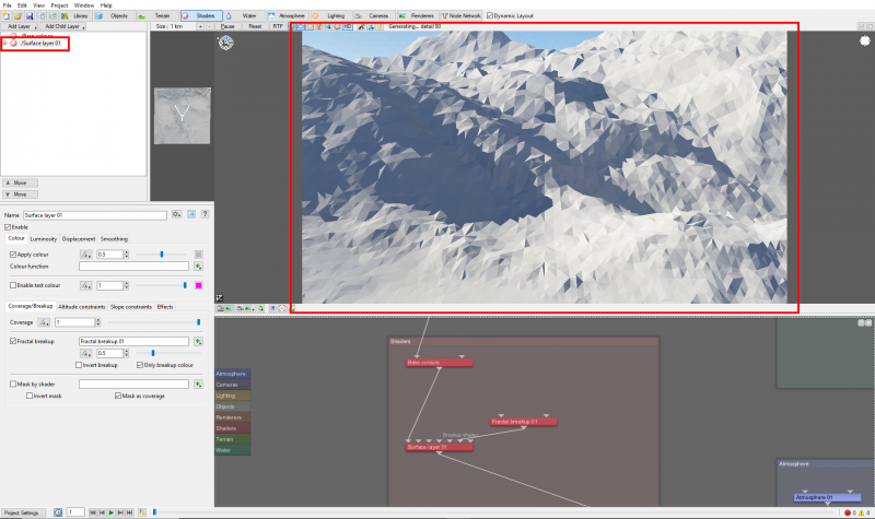
Add a new Surface Layer to the Terragen scene by clicking on the “Shaders” button under the Main Menu, then click the “Add Layer” button and select “Surface Layer”. The immediate effect of adding a Surface Layer is to overwrite all the colour information of the shader nodes upstream from it, such as the Base colour node.
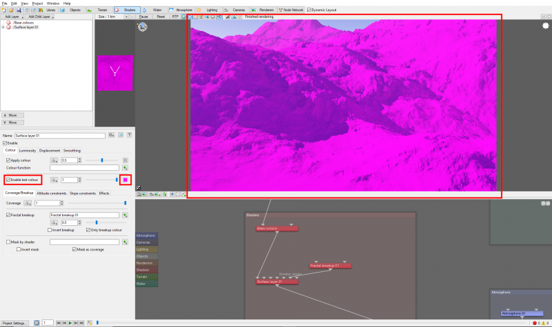
Before we start applying colour textures to the terrain we need to decide which areas will have vegetation and which areas will remain bare and rocky. To help us visualize this distinction click on the checkbox to the left of the “Enable test colour” parameter. The terrain will turn the colour indicated by the color swatch to the right of the “Enable test colour” parameter.
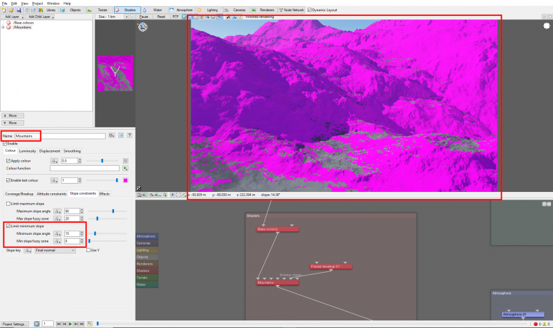
For this tutorial, we can define the bare mountainous areas to be the terrain with slope angles greater than 15 degrees and the vegetation areas to be the flatter areas of the terrain with slope angles less than 15 degrees. Rename the Surface Layer to “Mountains” and under the Slope constraints tab, enable the “Limit minimum slope” checkbox and set the “Minimum slope angle” value to “15.0” degrees and the “Minimum slope fuzzy zone” value to “0.0”. The 3D preview will update, displaying the mountainous areas in the test colour.
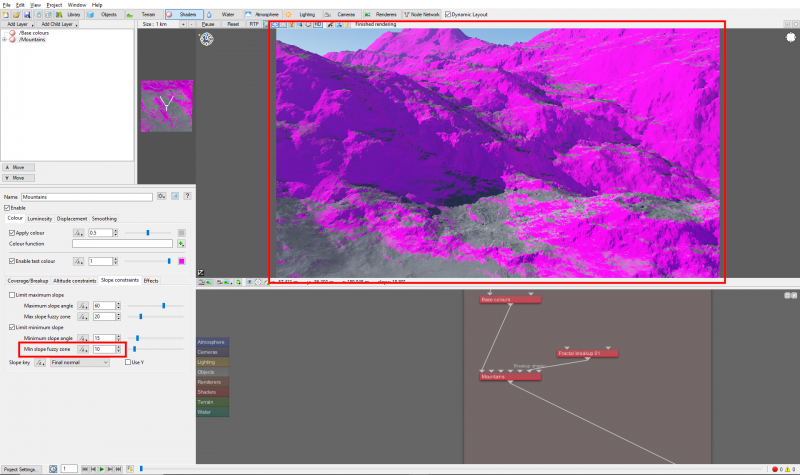
The hard, jagged edges are due to setting the Minimum slope fuzzy zone value to 0.0. This parameter controls the blending curve between transparent and opaque, in other words, it creates a soft gradient transition between a Surface Layer and the nodes beneath it in the workflow. For more information on “fuzzy zones” click here. Set the “Minimum slope fuzzy zone” value to “10.0”, to soften the hard edges between the bare rock and the vegetation regions.
Mountain and Cliff textures[edit]
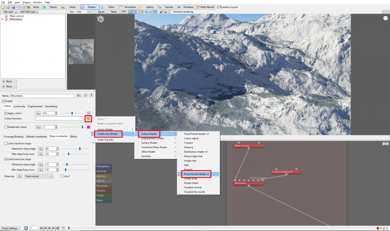
Now, we can begin to texture the mountain areas. Start by unchecking the “Enable test colour” checkbox. We could pass the colour values from the Base colours node to this Surface Layer by unchecking the Surface Layer’s “Apply colour” checkbox, or add new colours by assigning a shader or function node to the Surface Layer’s “Colour function”. Click on the green “Plus” button next to the Colour function, then select “Create new Shader”, then “Colour Shader”, then “Power fractal shader v3”.
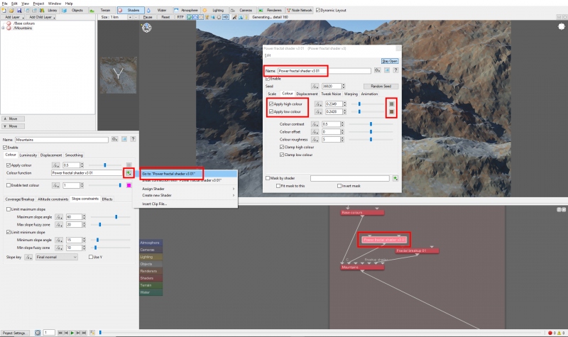
Open the dialog window for the Power fractal shader by double clicking on it in the Node Network pane or clicking on the green “Plus” button next to the Colour function, then selecting “Go to Power fractal shader v3”. Rename the node to something descriptive like “Mountain Colours”. On the Colour tab, click on the colour swatch to the right of the “Apply high colour” slider and choose a green colour such as RGB values 132,132,121. Then enable the “Apply low colour” checkbox, click on its colour swatch and give it a brown colour such as RGB values 134,101,76. On the Displacement tab uncheck the “Apply displacement” checkbox.
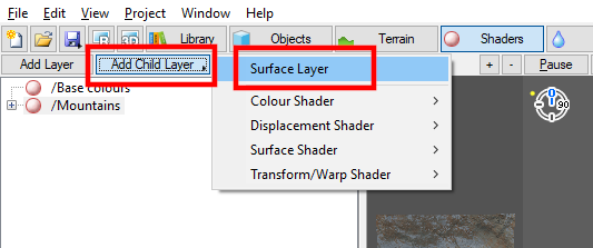
We want the steepest cliffs of the mountains to have their own texture, so with the Mountain Surface Layer selected, click the “Add Child Layer” button and select “Surface Layer”.
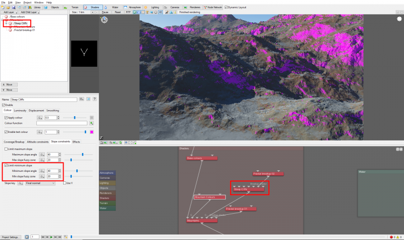
Just as before, the child Surface Layer has overwritten all the colour information from the shader nodes upstream of it, but this time it’s limited by the constraints of its parent Surface Layer. Click the checkbox next to “Enable test colour”. Under the Slope constraints tab enable the checkbox to “Limit minimum slope”, then set the “Minimum slope angle” value to “40.0” and the “Min slope fuzzy zone” value to “20.0”. Rename the child Surface Layer to something descriptive like “Steep Cliffs”.
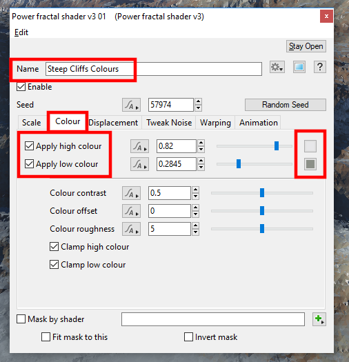
We will use the same techniques to apply colour to the Steep Cliffs Surface Layer as we did for the Mountain Surface Layer. First uncheck the “Enable test colour” checkbox, then assign a new Power fractal shader to the “Colour function” of the Steep Cliffs Surface Layer. Rename the Power fractal shader to something descriptive like “Steep Cliff Colours”.
On the Colour tab click on the colour swatch to the right of the “Apply high colour” slider to bring up the Colour Picker and select a gray colour with RGB values of 231,231,233. Then enable the “Apply low colour” checkbox and in the same way choose a darker grey value, like RGB values 140,144,137.
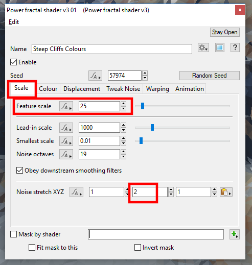
On the Scale tab, increase the “Feature scale” to “25.0” and the “Y” component of the “Noise stretch XYZ” parameter to “2.0”.
Vegetation textures[edit]
Next we will create a parental hierarchy of multiple Surface Layers that when blended together will define the base colours of the vegetation on the mountains. We want the vegetation colour to evolve from cool greens to warm reds as the terrain elevation increases. The initial colours we choose can be adjusted and fine tuned at the end of this step.
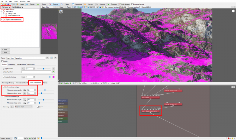
Add a new Surface Layer and give it a descriptive name like “Light Green Vegetation” and check the “Enable test colour” checkbox. Enable the “Limit maximum slope” checkbox under the Slope constraints tab, and set the “Maximum slope angle” value to “40.0” and the “Max slope fuzzy zone” value to “30.0”.
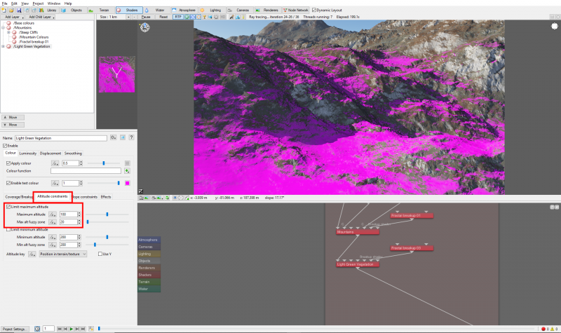
To constrain how high the vegetation grows up the terrain, enable the “Limit maximum altitude” checkbox under the “Altitude constraints” tab, and set the “Maximum altitude” value to “100.0” and the “Max alt fuzzy zone” value to “20.0”.
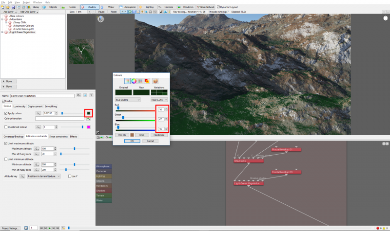
Uncheck the “Enable test colour” and then click on the “Colour Swatch” to the right of the “Apply colour” slider to bring up the Colour Picker dialog. Choose a dark green value like RGB 16,48,16.
It’s worth noting here that the Colour Picker temporarily converts and displays the colour swatches in sRGB values, from 0-255, while the parameter view slider represents the largest of the 3 RGB values in linear space. Internally, however, Terragen calculates everything in linear colour space.
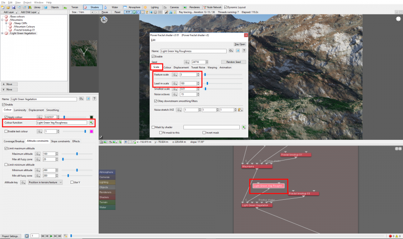
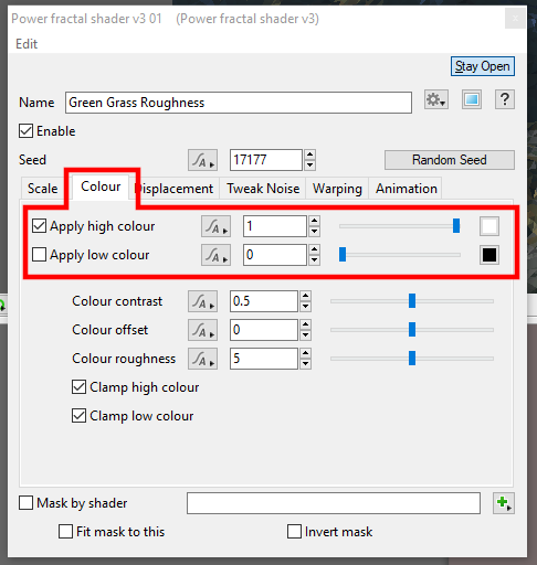
Assign a new Power fractal shader to the “Color function” and open up its dialog window and give it a descriptive name. The purpose of this Power fractal is to create colour value variations based on the colour chosen in the Surface Layer’s “Apply colour” parameter. It does this by choosing a random value between the colour components of the Power fractal shader’s “Apply high colour” and “Apply low colour” and multiplying that value by the colour component of the Surface Layer “Apply colour” parameter.
By default the Power fractal’s high colour is enabled and set to white, or 1.0, and the low colour is disabled, which means that a fractal pattern between the values of 1.0 and nothing, or 0.0, will be created and multiplied by the Surface Layers “Applied colour” component values, which are currently dark green. So we end up with shaded green values in our terrain.
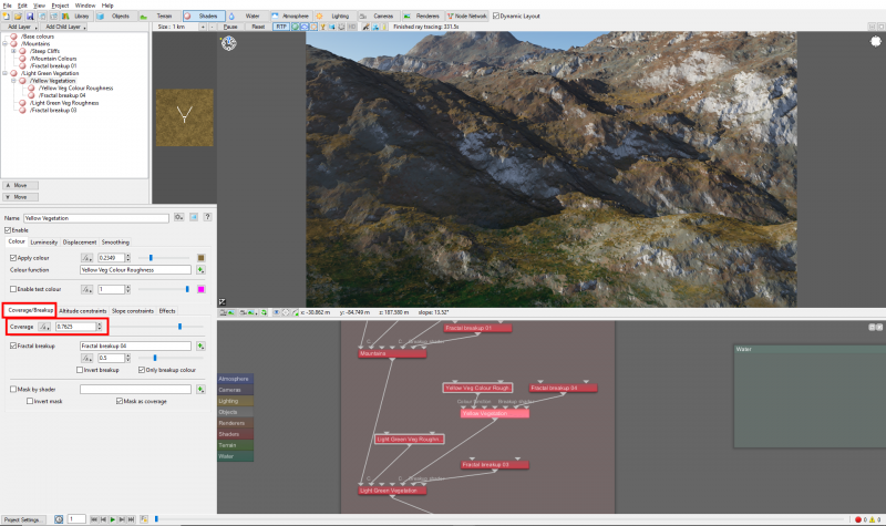
Let’s add a little more colour to the terrain by adding “Child Layer” and naming it “Yellow Vegetation”. The effect of a child layer is constrained to that of its parent, but we can still apply additional constraints. Enable the “Limit minimum altitude” checkbox and set the “Minimum altitude” value to “-100.0” and the “Min alt fuzzy zone” value to “35.0”.
Give its “Apply colour” a dark yellowish brown colour like RGB 132,108,59 and then assign a new Power fractal to the “Colour function”. Enable its “Apply low colour” parameter and give it a RGB color value of about 150,150,150.
We can control the opacity of this Surface Layer via Coverage/Breakup tab, by reducing the “Coverage” value to about “0.7625”. Lowering the value allows the surface beneath to show through.
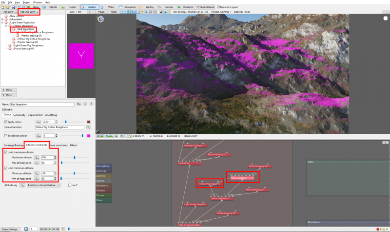
Let’s add one more colour to our terrain by adding a Child Layer to the Yellow Vegetation Surface Layer. Name this one “Red Vegetation” and give it a dark reddish colour.
In Terragen you can often reuse or share nodes between different functions, so let’s share the Power Fractal node used for the “Colour function” in the Yellow Vegetation Surface Layer by connecting its output to the “Colour function” input of the new Red Vegetation Surface Layer.
The Red Vegetation Surface Layer is both overriding its parent, the Yellow Vegetation Surface Layer, and being constrained by it. Enable its “Test colour”, and then enable the checkboxes for “Limit maximum altitude” and “Limit minimum altitude”. Set the “Maximum altitude” value to “100.0” and the “Max alt fuzzy zone” value to “50.0”, and then set the “Minimum altitude” value to “-80.0” and the “Min alt fuzzy zone” value to “35.0”.
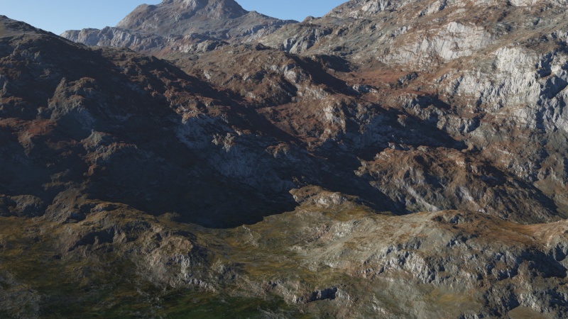
Reduce the Red Vegetation Surface Layer’s coverage to around “0.8”, and then render a frame so we can review the settings and make adjustments to the colour values or opacity.
Snow textures[edit]
The last surfacing technique we want to cover is applying snow caps to the top of the mountains. The same techniques are used to create surface layers for each important level of snow. What’s new in this step is a type of mask we’ll create to limit these types of snow layers. The goal we want to achieve is to have greater snow density on the shadowed side of the mountains and less snow on the sunny side. We’ll do that by sampling the terrain’s geometry to determine the direction the polygon normals are facing and then select only those that face in the direction we want. This will give us a mask, that we can then adjust to our liking.
Start by adding a new surface layer and calling it something like Deep Snow Depressions.
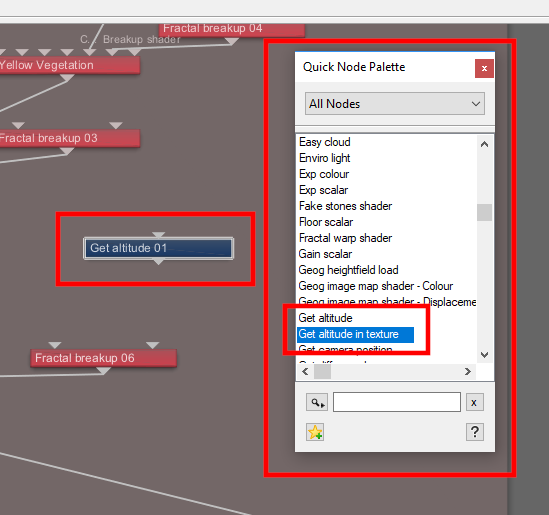
Click once in the Node Network layout to activate it, then press the “Tab” key or the “N” key on your keyboard to bring up the Quick Node Palette. If you start typing a word on your keyboard at this point, the Quick Node Palette will search for that pattern and reposition the node list to the closest matching item. Start typing the word “Get”, then highlight the “Get normal in texture” node and press the “Enter” key to add the node to the Node Network layout. Do the same for a “Constant vector” node and a “Dot product” node.
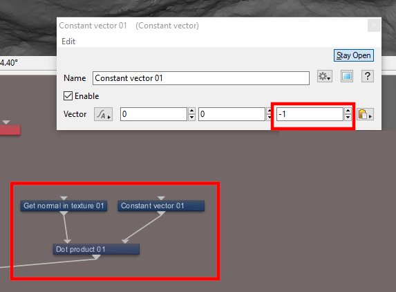
By connecting these nodes together we can tell Terragen which side of the mountains we want the snow on. Click on the “Output” triangle of the “Get normals in texture” node and drag out a connecting line to the “Main input” the “Dot Product” node. Connect the “Output” of the “Constant vector” node to the “Input 2” of the “Dot Product” node in the same way. We determine which mountain side the snow texture will lie on by entering a value between -1.0 and 1.0 in the “Constant vector” node. Double click on the node to open its dialog pane and enter the value “-1.0” in the third box which represents the Z axis vector. The Dot product node outputs a mask by evaluating the direction the geometry normals are facing and keeping those that face in the direction supplied by the Constant vector node. Connect the Dot product node “Output” to the “Mask shader” input on the Deep Snow Depressions Surface layer to see the result.
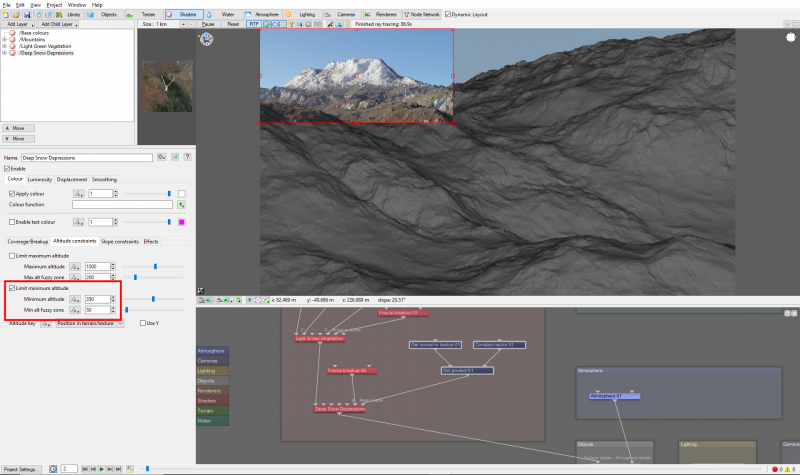
Let’s constrain this Surface layer to only the upper altitudes of the Mountain range. Enable the “Limit minimum altitude” checkbox and enter a value of “350.0” for the “Minimum altitude” and “50.0” for the “Minimum alt fuzzy zone”. Also set the Surface Layer’s “Apply colour” value to “1.0” so that the colour is at its strongest.
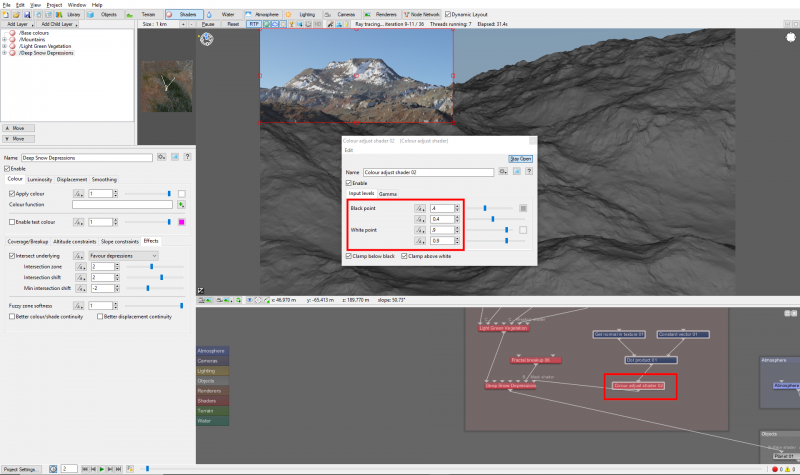
Add a “Colour adjustment” shader node via the Quick Node palette and connect the “Output” of the Dot product node to the Colour adjustment shader’s “Main input” to further refine the area the snow is applied to. Double click on the “Colour adjustment” shader node to open its dialog and adjust the “Black point” and “White point” sliders until you’re happy with the result. For this demo, increasing the “Black point” value has the effect of reducing the area covered by the snow and decreasing the “White point” intensifies the snow in the areas that are covered. One last thing to try is to enable the “Intersecting underlying” parameter on the Surface Layer’s Effects tab and choose “Favour depressions”. This works by sampling a smooth version of the terrain against its final version and masks the result to the areas lower or in the “depressed” regions..
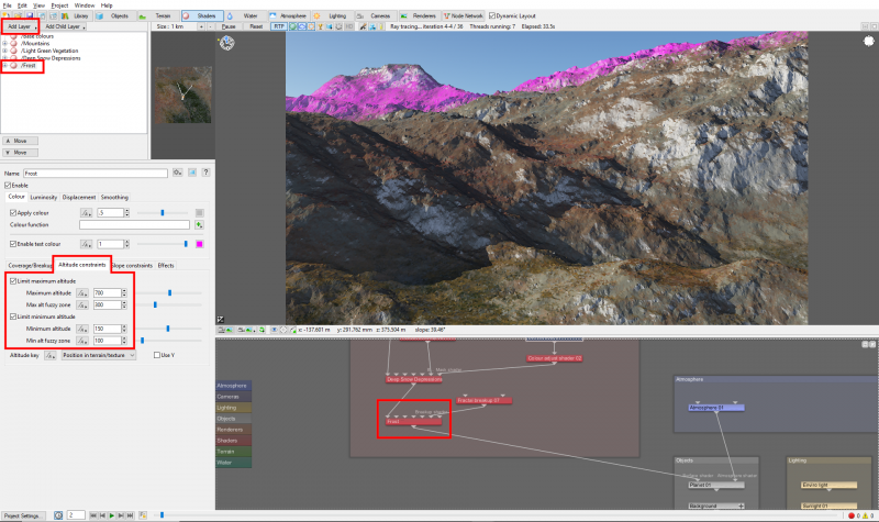
Next we want to create a light dusting of snow over the rest of the mountain. Add another surface layer, rename it FROST and set its “Minimum altitude” value to “150.0” and the “Minimum alt fuzzy zone” to “100.0”. Enable the “Limit maximum altitudes” checkbox and set the “Maximum altitude” value to “700.0” and the “Max alt fuzzy zone” value to “300.0”.
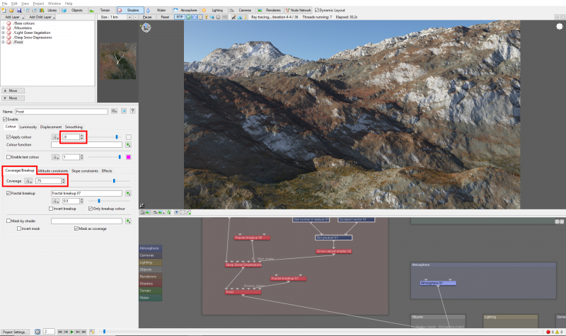
Raise the Surface layer’s “Applied colour” value to “0.9” to make it slightly less white than the Snow Deep Depression Surface layer. Then reduce the opacity of this Surface Layer by reducing the “Coverage” value to “0.75”, which will allow the Surface Layers below it to show through a bit.
We’ll add one last Surface Layer and rename it “High Frost”, whose purpose will be to make sure there is snow at the very crest of the mountain top. Limit its “Minimum altitude” value to “550.0” and its “Minimum alt fuzzy zone” value to “60.0”. Set its “Apply colour” value to “1.0” and its “Coverage” value to “0.95”.
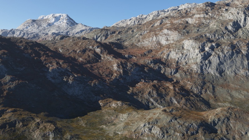
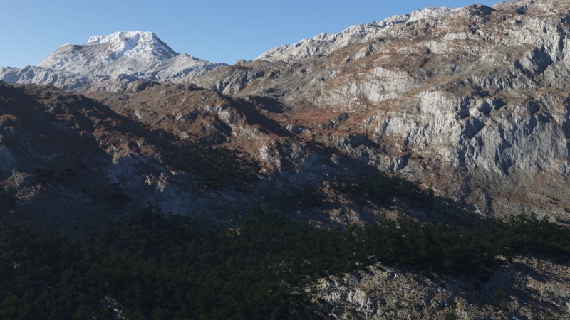
As you can see in these final renders, using Surface Layers gives you the flexibility to create and blend between textures using many forms of constraints such as parent - child hierarchies, altitude and slopes.
A parameter is an individual setting in a node parameter view which controls some aspect of the node.
A shader is a program or set of instructions used in 3D computer graphics to determine the final surface properties of an object or image. This can include arbitrarily complex descriptions of light absorption and diffusion, texture mapping, reflection and refraction, shadowing, surface displacement and post-processing effects. In Terragen 2 shaders are used to construct and modify almost every element of a scene.
A single object or device in the node network which generates or modifies data and may accept input data or create output data or both, depending on its function. Nodes usually have their own settings which control the data they create or how they modify data passing through them. Nodes are connected together in a network to perform work in a network-based user interface. In Terragen 2 nodes are connected together to describe a scene.
Literally, to change the position of something. In graphics terminology to displace a surface is to modify its geometric (3D) structure using reference data of some kind. For example, a grayscale image might be taken as input, with black areas indicating no displacement of the surface, and white indicating maximum displacement. In Terragen 2 displacement is used to create all terrain by taking heightfield or procedural data as input and using it to displace the normally flat sphere of the planet.
The Node List is a part of the Terragen interface that shows a list of nodes along the left side of the application window. The Node List generally shows only those nodes that are relevant to the current Layout (e.g. Terrain, Atmosphere). It sometimes includes buttons or other controls that are specific to a particular Layout as well. The Node List is hierarchical and each level is collapsible.
A vector is a set of three scalars, normally representing X, Y and Z coordinates. It also commonly represents rotation, where the values are pitch, heading and bank.
