Terrain and Water
Contents
Introduction[edit]
The terrain is one of the most fundamental building blocks of any scene. Terragen 2 has several flexible systems for creating the terrains that you will base your scenes on and it is important to understand how each one works so that you will know which is most appropriate for a given need.
In Terragen 2 you work with two related but notably differing terrain types – heightfields and procedurals. In general you can think of heightfields as finite in area and limited in the detail they can present, but capable of presenting very specific terrain shapes (such as real-world elevation data) and being easily edited and widely compatible with other programs. Procedurals on the other hand are generally capable of covering unlimited area with unique detail and can depict a very large range of scale at high detail, but they are more difficult to make intuitive, specific changes upon and they are less compatible with other applications.
Welcome to the World of Procedurals[edit]
Terragen 2 operates in a fundamentally different way from previous versions. Although previous versions of Terragen did use procedurals for some functions, and Terragen 2 still has robust heightfield support, it is now much more focused around the use of procedurals to create everything from the clouds in the sky to the shape of the terrain itself. The creation of the terrain through procedurals is particularly significant since it allows for terrains that are truly unlimited in size and detail, unlike the finite resolution raster heightfields you may be used to dealing with in Terragen or other landscape applications.
Procedurals are simply mathematical functions that can create visual output, which can then be used in many practical computing applications. Fractals are a type of procedural which you may already be familiar with. The mathematical basis of procedural functions allows them to portray very large ranges of scale. Simply changing the input values of a function can allow it to depict anything from mountains to pebbles and everything in-between. This also allows for nearly infinite detail to be portrayed in a scene based on procedurals.
Common “heightfields” or “heightmaps” are a form of “raster” data, meaning they are defined as an array of pixels or samples of finite dimensions. So most heightfields, such as Terragen .ter files or DEM’s, have a finite detail level defined by the resolution of the heightfield in pixels. Procedurals do not have this kind of limitation since they can be generated and sampled at virtually any scale as needed. Technically speaking Terragen uses procedurals as heightfields by sampling the procedural at regular intervals to derive height values, however for the sake of clarity we will simply refer to them as procedurals and to so-called “raster heightfields” as simply heightfields.
What’s In The Details?[edit]
In “Your First Scene” we looked at some of the immediate benefits of procedurals in portraying large scales. We saw that whole planets could be created very easily by a single procedural function. If you haven’t reviewed that section yet, please read through it before moving on. So now let’s look at the other end of the Procedural spectrum – micro-scale.
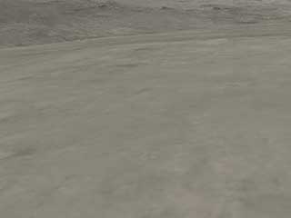
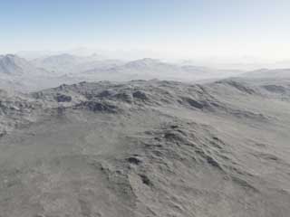
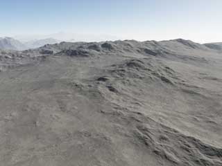
Replace the heightfield in the default scene with a procedural, as described in Your First Scene. Name the new node “Mountains”; it will form the basis of our terrain in this exercise. Adjust your camera as needed so that it is looking at the nearby ground and then move down as close to your terrain as you can without going under it. Remember to use the Vheight display to check your height above the terrain; 2-3 meters is probably a good height. When you have gotten as close as you reasonably can, press the Set Camera button, open the Render View (F3 or the R on the toolbar), and render your scene. You will see a reasonable amount of detail already, but it is overly smooth; it could be much more detailed and three-dimensional.
To add some detail we will create another procedural terrain layer, but this time we’ll make the scale much smaller. This will allow us to maintain our overall large-scale terrain shapes while adding detail at smaller scales. First create another Power Fractal terrain layer from the Terrain layout by going to the node list and using the Add Terrain button. You will see your terrain change quite drastically, but don’t worry we’re going to tone it down a lot.
Click on the new Power Fractal to bring up its settings for editing and give it a name like “Detail Layer”. Remembering that most units in Terragen are specified in meters, let’s turn the Feature Scale down to about 0.1. This means our average feature size is now going to be 1/10th of a meter -, 10 centimetres - or about 4 inches. We will want to adjust the Lead-in scale and Smallest scale to give us some good range on either side of that as well. Set Lead-in scale to around 2 and Smallest scale to around 0.02. Our smallest features will be around 1/50th of a meter and the largest around 2 meters.
Your scene still probably looks a lot different than before but there is one last setting we need to adjust to set things right. Go to the Displacement tab of the Power Fractal and look at the Displacement amplitude. This setting controls the actual height of the displacement applied to the terrain by this node and at the default of 1000 meters you can understand why it is making your terrain look so much different. Set it to 1 and you should see your scene return to something more normal, but now with a noticeable increase in smaller-scale detail. Start a test render to see the result of your changes.
When the render finishes you may notice that, although there is additional detail, it is somewhat harsh and unnatural looking. Let’s tweak our settings a bit to get a more varied and realistic look. Go back to the Power Fractal’s settings and take a look in the Displacement tab again. Our current amplitude is 1 meter, but with a Feature scale of 1/10th of a meter it makes sense to reduce this to about the same. Let’s set it to 0.1 to match our Feature scale. The look of the fractal shapes also wasn’t exactly as we may want so let’s change the Noise “flavour”. Go to the Tweak Noise tab and at the top click the drop-down box for Noise flavour to see the available options. Currently it is set to Perlin mix 1, a mix of standard Perlin and Perlin billows noise types. Let’s see if Perlin mix 2 gives us a nicer look.
While we’re in the Tweak Noise tab we want to try to give our small features a bit more variety. Noise variation is already at 2, a medium setting, but let’s increase that to 3 for a bit more variety. It might be nice if our small features also formed small clusters, like natural wind-born deposits, so let’s increase Clumping of variation to 0.5. Now that we have tweaked the settings a bit more to try to achieve a more natural look, let’s do another render and see how we did.
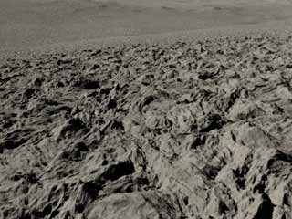
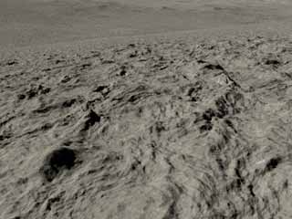
As it renders you will see that now, even at this small distance from the terrain, there is still a tremendous amount of detail. This clearly illustrates the tremendous power of procedurals in depicting things both large and small, with the simple combination of these two Procedural terrain node creating an entire planet of terrain from mountains down to tiny rock-like formations. You can also use even more layers of procedurals to vary the detail across the terrain or create realistic large and small scale features, allowing fully realistic virtual planets to be created, with detail from continent level down to the sand on a beach.
Terragen 2 makes use of this tremendous flexibility and scalability not only to create highly detailed, infinitely varied global landscapes, but also to add detail to your imported, generated, and edited heightfields, allowing you to have the best of both worlds. Learn more about how to accomplish this in the Heightfields section below.
Bigger Is Better: Large Scale Terrain Features Using Procedurals[edit]
The other part of the recipe for fully realistic planets is large-scale features. We have seen how Terragen 2’s procedurals can create realistic detail on the scale of mountains across an entire planet and how the same fractal detail can be used to increase detail even down to very small scales. Now we’ll find out how to create larger features like continents and mountain ranges. Creating large scale detail to cover an entire planet is challenging, but with some patience and practice you can create entire planets with realistic terrain features and virtually infinite variety.
In general it’s as simple as you might think it is – increase the Feature scale to suitably large levels and blend with your other terrain shapes. Depending on what you want to achieve that may be all you need to know. But we’ll also look at some slightly more advanced methods of achieving terrain shape variations across larger scales, rather than simply adding large displacement over the whole planet.
Let’s start with the simple method, based on the scene we created in the previous section. If you haven’t yet reviewed that section, simply create a Power fractal node in a new scene and leave the settings at the defaults. Name the new node “Mountains” – we’ll be creating several more terrain nodes later and it will help to keep track of it more easily.
Before we begin adding larger features you will want to move your camera to a fairly high altitude to avoid your view being stuck inside the terrain; 1-2km of altitude should suffice. You should do a test render from the new camera perspective so that you have a reference point.
Now create a new Power fractal node (the 3rd one if you are adding on to the previous scene, or the 2nd one created if you are starting from scratch). Name this one “Large Features”. The most important thing we’ll be doing is changing the Feature scale and Lead-in scale. This will give us the larger shapes we’re looking for. Let’s try initial values of 50,000 for Feature scale and 250,000 for Lead-in scale – 10 times the defaults. With an average feature size of 50km, this should help us easily depict features on the scale of mountain ranges and coastlines. Do another test render to see what the immediate difference is.
The differences in your scene will probably vary a great deal from the provided example, but hopefully you do see a change since adding the new Power fractal and tweaking the settings. If not, try moving your camera to a new location. You can disable the new node temporarily to see a before and after view – simply uncheck the Enabled checkbox in the upper-left of the node’s settings. If you can’t find a view that shows much difference don’t worry, we’re going to take off into orbit in a moment where we’re sure to see some big changes.
Before we do that let’s talk about the changes illustrated in the example scene. Although the feature scale is very large, you will notice that the change in height of the affected features was comparatively small – it was certainly not 50km high! This is because the Displacement amplitude controls the actual displacement “strength” separately. Let’s go to the Displacement tab of our large-scale Power fractal node and increase the effect a bit. The default Displacement amplitude is 1000 meters, a good setting for average mountains. Although large-scale features aren’t always particularly tall, we’re going to increase this to about 1500 for effect. Another test render is probably in order.
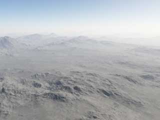
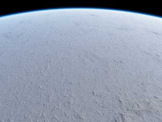
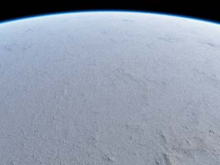
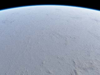
The effect is a bit more dramatic now, and hopefully visible from orbit. Let’s take a look. Using the camera controls described previously, point your camera down at the planet and use the Zoom function to rapidly gain some distance from your planet. When you’ve reached a suitable height adjust your view so that you see a good portion of the planet, including the edge. You should be close enough so that the planet could fill your field of view. Make sure you set the camera view and then do another test render.
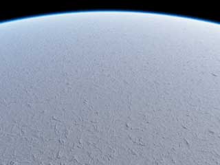
For comparison let’s turn off our “Large Features” node and see what things look like from this vantage point. Use the Enable checkbox to turn off the node and do another render.
Although the differences are a bit subtle, they are noticeable even from this high altitude, which means that they must be quite large. We have a good start on the mountain range and continent-scale features we are looking for. You will notice however that the majority of the world is covered in our mountain shapes and it looks much too evenly distributed. The next step is to try to limit their coverage in a more realistic way to achieve unique features like mountain ranges, canyons and open plains.
For the next step we will need to work directly in the node network. We’ll be creating a procedural function to define the area where our mountains will be distributed and connecting it to the Blend shader input of our “Mountains” node to limit its coverage. You can remain in the Terrain layout and simply use the smaller network view on the lower-right, or you can switch to the larger Node Network layout. In either case we will want to start by zooming in the Terrain group.
Now right-click an empty area inside the group and choose Create Shader, then Surface Shader, and finally Power fractal shader v3. Name this new device “Mountain Distribution” then left-click on the output at the bottom of the device and drag a connection to the Blending shader input on the right of your “Mountains” Power fractal node.
Blending shader inputs are present on most shader nodes. The effect of this input, when enabled, is similar to a “mask” in other applications. Using a typical masking interpretation of the input this function lets you use greyscale imagery and procedural outputs to control distribution of a node. As is typical in other applications white is “full coverage” and black is “no coverage”, with grey values in-between representing varying levels of coverage.
Before we can see the effect of our new blend shader we need to enable blending in our “Mountains” node. At the bottom of the node’s setting window you will see the Blending input controls. You should see the name of your blending shader next to the “Blend by shader” check box. Click the box to enable “Blend by shader” and the blending function will be activated. You should see an immediate change in the preview window, although it may be subtle. Try a test render to see what result the default settings produce.
You should see some difference but it may not be immediately clear what has been changed. Essentially you are masking your mountain shapes at a default Feature scale of 5000 meters with another node at a similar scale. This produces a fairly random-looking general reduction in mountain distribution and a decreased height overall. In order to get a better distribution we’ll need to adjust scale.
Unlike the node list when you are in the node network you need to double-click a device to bring up its settings. The settings window will actually come up as a floating window which may be moved around freely, closed like a normal window, or keep open permanently with the “Stay Open” button. Refer to the Node Network section above for more detail. Once you have the settings window open adjust the Feature scale and Lead-in scale to something suitably large, similar to our “Large Features” layer created previously. Let’s try 65,000 for Feature scale and 325,000 for Lead-in scale. This gives us average features 65km in size, which is a bit small for normal mountain ranges, however because our Lead-in scale is quite a bit larger we should get a nice variety of larger features as well.
We’ll also want to increase the Smallest scale since we really don’t need this node to operate at such a wide range. Keep in mind that the more octaves of noise generated, the longer the shader will take to calculate. Set the Smallest scale to about 50 meters – this will reduce calculation time while still providing enough small-scale detail to be realistic. If Smallest scale, Lead-in scale and Feature scale are too similar you will have very few octaves of noise which gives the output a very artificial look.
Let’s do another test render so we can determine what to adjust next.
The mountains are now less random-looking, but also much less prominent in general. We will want to increase the differentiation between areas with and without mountains by adjusting the contrast of the blend shader node. This should give us both higher mountain peaks and smoother plains.
Begin by going to the Color tab of the “Mountain Distribution” node. You will see the default Color contrast is only 0.5 so let’s increase that to 1.0. The Color roughness is also rather high by default, which will tend to result in undefined edges on our mountain chains. Reduce the roughness to about 2.0 for a more defined and less random look.
You may have also noticed that the default Perlin noise function doesn’t really create shapes that are appropriate for mountain ranges. Let’s see if we can find a suitable alternative. Go to the Tweak Noise tab and take a look at the options in the “Noise flavour” drop-down. Perlin ridges seems to provide a better base structure so we’ll select that for now.
Heightfields[edit]
With Terragen focusing so heavily on procedurals and their obvious advantages, the uses and advantages of heightfields can easily be overlooked. But heightfields are still very useful in a procedural world and the best scenes will often come from effective combinations of both types of terrains. Procedurals are great for creating lots of random detail over a large range of scale, from very large to very small. Heightfields on the other hand are good at presenting very specific shapes and generally portray a smaller range of scale more effectively. So for example if you wanted an entire planet of terrain a procedural function would really be the only practical approach, but if you want to have a realistically eroded and shaped terrain with specific features, a heightfield is your best bet.
Fortunately with Terragen 2 you don’t have to choose. Not only can Terragen mix procedurals and heightfields quite easily in a single scene, it can also very effectively use a heightfield as a basis to form a realistic underlying terrain shape and build on it with procedurals to create very high detail, realistic scenes. You can easily import a DEM of a real place to establish a highly realistic basic terrain shape then add fine procedural details to create a realistic foreground. Or use a heightfield for your local area of terrain and use procedurals to fill in the background and avoid the “end of the world” or “flat planet” syndrome. You can also use multiple heightfields, even at different resolutions, to define different areas and scales of your terrain. The possibilities are virtually limitless!
By default any heightfield loaded into Terragen 2 will have some amount of “fractal detail” applied to it. This provides unobtrusive additional detail below the scale of the smallest features in your base heightfield, adding realism and avoiding sharp polygon edges without compromising the shape of your terrain. You can control how the fractal detail is applied to your heightfield in the Fractal Detail tab of the Heightfield Shader.
This randomized, small scale fractal detail is great for making your heightfields more realistic and fitting them more easily into a procedural landscape but the controls are minimal and the detail added is not particularly interesting or significant. Fortunately you can use Terragen 2's powerful range of procedural shaders to affect the output of your heightfield and create more specific and interesting effects, including overhangs. Let’s see how we can use procedurals to create realistic overhanging cliffs using a canyon DEM as a base.
You can also use more than one heightfield or increase the size of your heightfields, but we will explore those options later.
Water[edit]
Currently there are two ways to create water: you can use the built-in Lake object, which creates a flat circular disc of water at an adjustable size, or you can apply a Water Shader to to your terrain and use a blend shader or other form of masking to control its placement. With the Lake object, you have the ability to create multiple unique water elements at different heights and with different color and wave characteristics. You can even mask the water shape for fine control over its distribution, allowing the creation of rivers, intricate lake shapes, and other important elements. Let's take a look at how to actually use the Lake object in more detail.
First go to the Water layout so we can place the Lake object. It's the only option currently available on the Add Water Object menu and you will immediately see your 3D preview window covered with water when you add it. After you have done so, click on it in the node list to bring up its settings.
Most of the controls here are fairly self-explanatory. At the top the normal naming and enable/disable control. Handle In Preview determines whether the lake object itself will be shown in the viewport. Cast Shadows will be seldom used for now but its effect is fairly obvious - it makes the water disc cast shadows onto the terrain.
Moving on let's look at the settings on tne Transform tab. the Water Level is literally just the height of the object above the base planet surface (this will be important when transparency is introduced in later versions). The Centre settings control the X, Y, Z placement of the object and can be used when precise placement of your water is needed, but it's generally easier just to drag it around in the viewport. And finally Max Radius allows you to control the size of the lake object, measured in meters as usual.
The Planet and Surface Shader tabs are extremely simple. Planet allows you to specify the planet this water object is associated with. Because it's a flat disc it needs to be adjusted to fit the curvature of the planet, especially at large radius values, so it's necessary to connect it to a Planet to accomplish these changes. The Surface Shaders tab simply defines the shader for the lake object; naturally it defaults to a Water Shader.
Now that we've looked over the basic settings let's do a quick render to see how the water looks. Keep in mind that the default camera perspective is 1 kilometer above the terrain, so let's move down a bit to see the water better. Take the camera down until it seems fairly close to the water- about 200 meters - and do a render from this new camera position. At this height you should be able to see the wave structure as well as the wave variation which helps to increase realism. You'll no doubt find that water takes a bit longer to render than most other scene elements. Reflections are always quite demanding to render and Terragen 2 is no exception, but this aspect will be getting a lot of optimization in the future to improve things as much as possible.
You can control all aspects of the water surface itself in the Water Shader settings. Let's take a look there now and see what kind of things can be done with the current functionality. From the Surface Shaders tab click the box to the right of the Surface Shader name (Water shader 01) and select Go to [shader name] and the water shader settings window will then be opened. Aside from the standard node controls there are only two tabs here that allow you to control all aspects of your water. In the future additional functions such as transparency and shore surf/foam will probably have their own tabs here. For now the Wave tab is visible and contains some of the most important controls to adjust the look of our water.
By now you should be familiar with naming conventions of Terragen 2 so hopefully most of these will be self-explanatory. The Roughness setting controls the general roughness of the water surface and in combination with the Wave Scale and Smallest scale it determines the majority of the water shape. Wave Scale is the average wave size and Smallest Scale determines the size of the smallest details - increase this if the water shape looks too simplistic, but reduce it if you're only viewing the water from a distance as the smaller it is the more octaves in the Water Shader noise function and the longer render times will be.
The next set of controls should be familiar to users of Terragen 0.9 - the Wind Patch settings. In nature there are variations in wave structure and overall water smoothness across large bodies of water which is due to several factors including wind. These settings allow you to simulate those effects and bring an extra level of realism and needed variety and interest to large water elements. The defaults give a subtle variation to the water surface, modulating the roughness across the surface with a large-scale noise function. The Wind Patch Effect setting controls the strength of this effect - the actual amount of variation there will be between different areas. Wind Patch Size controls the average scale of the areas of variation. And finally Wind Patch Sharpness sets how sharp the line between areas of variation will be, or to put it another way it controls how smooth the transition between areas of different roughness is.
Now on to the Reflections tab. Master Reflectivity is fairly self-explanatory - it controls the overall level of reflectivity for the water. Index of Refraction is a technical term that refers to the amount of light refraction caused by a given material. This is implemented as the standard Index of Refraction where water is 1.33. The higher this is the more diffuse your reflections will be. Horizon Shift is a special function used to simulate the "shift" in reflection due to the aggregate effect of greater or lesser surface roughness on distant reflective surfaces. It will essentially shift the angle of distant reflection toward or away from the horizon. The easiest way to understand this is just to play with the slider and watch the effect on the preview. Highlight Intensity controls the strength of specular highlights from light sources and Min[imum] Highlight Spread allows you to control how much "spread" the reflections have - in other words how diffuse the specular highlights are.
Note that you can plug a shader into the Input of the Water Shader to override or contribute to many of these built-in settings. For example you can get more control over wave shape by plugging a Power Fractal into it and using the Displacement controls. A Heightfield Shader or Image Map can be used in the same way and can be particularly useful for explicitly controlling water shape. Another important capability enabled by the Water Shader Input is controlling the color of the water. Try plugging a Default Shader into the input and adjusting color - you now have the ability to specify any color you want for the water. This also gives us a springboard to our next experiment: masking the water to control its distribution.
A heightmap or heightfield is an array of height values, usually in a grid which describe the height at specific points in a defined area. Heightfields are used to represent real-world and virtual terrain in a specific, easily converted format. Most heightfields can be represented as simple image data in grayscale, with black being minimum height and white being maximum height.
DEM stands for Digital Elevation Model (or Map). A DEM is similar to a heightfield. DEMs are normally generated from real world measurements of a planet's surface, for example Earth or Mars.
In general a “procedure” is a series of steps that should result in a specific and reproducible outcome. In Terragen 2 a “procedural” is a mathematical function describing output which may be visualized and sampled to create anything from terrain to clouds.
In general a “procedure” is a series of steps that should result in a specific and reproducible outcome. In Terragen 2 a “procedural” is a mathematical function describing output which may be visualized and sampled to create anything from terrain to clouds.
In a graphical user interface (GUI) on a computer a toolbar is a row, column, or block of onscreen buttons or icons that, when clicked, activate certain functions of the program.
The Node List is a part of the Terragen interface that shows a list of nodes along the left side of the application window. The Node List generally shows only those nodes that are relevant to the current Layout (e.g. Terrain, Atmosphere). It sometimes includes buttons or other controls that are specific to a particular Layout as well. The Node List is hierarchical and each level is collapsible.
Literally, to change the position of something. In graphics terminology to displace a surface is to modify its geometric (3D) structure using reference data of some kind. For example, a grayscale image might be taken as input, with black areas indicating no displacement of the surface, and white indicating maximum displacement. In Terragen 2 displacement is used to create all terrain by taking heightfield or procedural data as input and using it to displace the normally flat sphere of the planet.
A single object or device in the node network which generates or modifies data and may accept input data or create output data or both, depending on its function. Nodes usually have their own settings which control the data they create or how they modify data passing through them. Nodes are connected together in a network to perform work in a network-based user interface. In Terragen 2 nodes are connected together to describe a scene.
A shader is a program or set of instructions used in 3D computer graphics to determine the final surface properties of an object or image. This can include arbitrarily complex descriptions of light absorption and diffusion, texture mapping, reflection and refraction, shadowing, surface displacement and post-processing effects. In Terragen 2 shaders are used to construct and modify almost every element of a scene.
