TGO Reader

Contents
Overview[edit]
The TGO Reader loads an object from a TGO file. TGO is Terragen's native object format, which allows the saving of Terragen-specific information such as internal surfacing networks, in addition to normal object settings. TGO is a Terragen-specific file format and is generally not supported in other applications. TGO Objects can be moved (translated), rotated, and scaled on the Transform tab. The Surface Shaders tab allows you to specify the surface shaders that will be applied to the object.
Node Type: Object
Settings:
-
Population mode: This popup has two options:
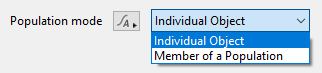
- Individual Object: This is the default for objects created individually, not part of a population. If you choose this option for objects that are part of a population the population instances will still render but the object itself will also show up at its original position.
- Member of a Population: This is the default for objects created as part of creating a population. It means the objects only render as part of a population. If you choose this option for an individual object it won't render.
If you create an object as part of a population and then decide to use it on its own you may need to change the popup to Individual Object to get it to render.
- Preview mode: This popup has five options and lets you choose how the object should be displayed in the 3D Preview by setting the most detailed mode that the object can be displayed in. The Object Display Mode button in the 3D Preview controls the mode for the preview as a whole. For example if you set the Preview mode of the object to Wireframe but the 3D Preview object display mode is set to Show as bounding boxes then the object will only be drawn as a bounding box.
- Preview Colour: Enabling this parameter causes the object to be drawn in the 3D preview using the preview colour when the object display mode is set to bounding box or wireframe. When set to smooth shaded or texture display mode, the preview colour tints the object’s textured surface. This is useful for making a particular object stand out in the 3D preview. Clicking on the colour swatch to the right of the parameter label opens the Colour picker pane.


File Read Tab[edit]

Settings:
- Filename: This parameter shows the path to the file used by the TGO Reader. You can use the file button at right to load a different file but this isn't recommended as the materials for the new file won't be loaded. To use an TGO file sequence you can use a limited set of C-style format strings to automatically insert the frame number, for example "MyObject_%04d.tgo" may result in "MyObject_0023.tgo" on frame 23, depending on the options on the Sequence tab.
Sequence Tab[edit]

Settings:
- Sequence first: When a supported frame insertion pattern is used in Filename to load a file sequence, Sequence first and Sequence last control the range of numbers that are allowed in the file sequence. If you have files with names MyObject_0001.tgo to MyObject_0010.tgo and want your animation to use them all, you would set Sequence first and Sequence last to 1 and 10 respectively.
- For example, when set to a value of 1, MyObject_0001.tgo will load on frame 1, when the Offset value is zero. If an Offset value other than zero is present, that value will be added to the Sequence first value to determine which geometry is loaded. For example, with an Offset value of “4”, MyObject_0005.tgo will load on frame 1.
- Terragen can cycle through a subset of the total available sequential geometry by specifying the range to use in the Sequence first and Sequence last values. For example, if the Sequence first value was set to “4” and the Sequence last value was set to “8”, then Terragen would cycle through the sequential objects named MyObject_0004.tgo through MyObject_0008.tgo. MyObject_0004.tgo would load on frame 4 and MyObject_0008.tgo would load on frame 8, if the Offset value were zero. Note, that frames 1, 2 and 3 would load MyObject_0006.tgo, MyObject_0007.tgo, and MyObject_0008.tgo respectively if Loop where enabled, and MyObject_0005.tgo, MyObject_0006.tgo and MyObject_0007.tgo if Ping pong were enabled.
- If the sequential object number does not exist, Terragen will display a warning message to alert you.
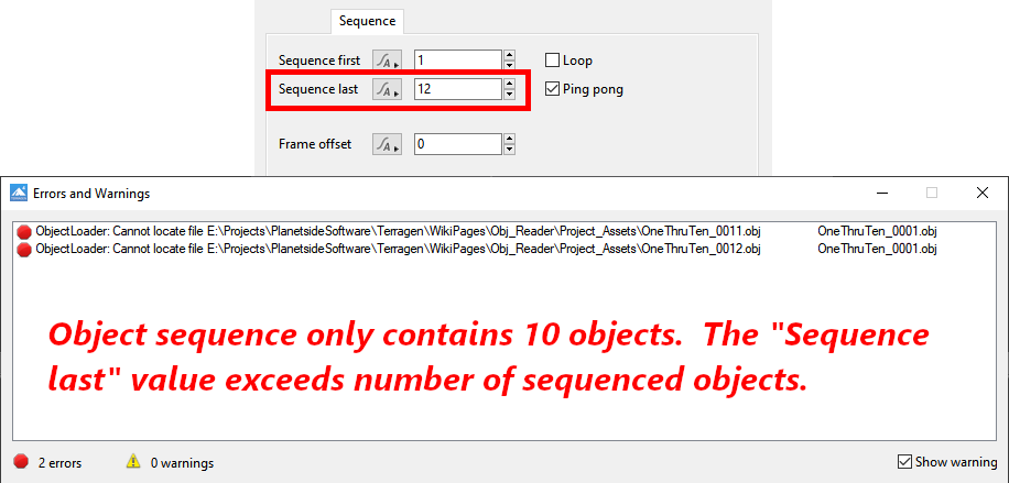
- Sequence last: When a supported frame insertion pattern is used in Filename to load a file sequence, Sequence first and Sequence last control the range of numbers that are allowed in the file sequence. For example, if you have files with names MyObject_0001.tgo to MyObject_0010.tgo and want your animation to use them all, you would set Sequence first and Sequence last to 1 and 10 respectively.
- If an Offset value other than "0" is present, that value will be added to the Sequence last value to determine which geometry is loaded, factoring in the number of available objects in the sequence and cycling through them based on the Loop or Ping Pong mode selected. For example, with an Offset value of “1” in a object sequence numbered 1 through 10, MyObject_0001.tgo will load on frame 10 if Loop is enabled, or MyObject_0009.tgo will load on frame 10 if Ping Pong is enabled.
- Loop or Ping Pong: After Terragen applies Offset to the current frame number, if the resulting frame number falls outside the range defined by Sequence first and Sequence last then Loop and Ping Pong are two different ways extend the cycle infinitely, both before the beginning and after the end of the sequence. Upon completion of the sequential object cycle determined by the Sequence first value and Sequence last value, the objects can either “loop” back to the Sequence first object and cycle through the objects as each frame advances, or “ping pong”, that is, reverse the object sequence order until the Sequence first object is encountered. If neither Loop nor Ping Pong are checked then the object will be held at the first or last file in the sequence when the requested frame number falls outside the defined range.
- Frame offset: This value provides a way to load files with sequential numbers that are different from the rendered frame numbers, to shift the timing of the animation or to account for differences in how the frames are numbered in the object filenames. Terragen adds Frame offset to the project's current frame number to determine which file number to load (with the actual file number being limited to the range defined by Sequence first and Sequence last with optional looping or ping-ponging). For example, if the Sequence first value is "1", the Sequence last value is "10", and the Offset value is "4", then MyObject_0005.tgo would be loaded on frame 1, MyObject_0006.tgo on frame 2, etc. Negative offsets can be used. For example, if the Offset value is "-1000" (negative), then MyObject_0001.tgo would be loaded on frame 1001, MyObject_0002.tgo on frame 1002, etc.


 |

|
 |

|
Mesh Modifiers tab[edit]

Read MDD (motion) file: Terragen can apply Motion Designer or “MDD” files created in third-party 3D software packages to an object within the project. The MDD file contains the position of every vertex in an object, for each frame of an animation. After an object is animated or otherwise deformed in the third-party 3D software, its vertex positions are “baked”, or saved in the MDD file format. This allows for complex animation to exist within a Terragen project, that otherwise could not.
 |
 |
 |
 |
Reverse Z (right handed): If the MDD file is facing in the wrong direction, you can reverse the Z axis in order to point it in the right direction.

Mesh displacer: The shader assigned to this parameter displaces the object’s vertices (mesh). For example, a power fractal shader can be used to displace the vertices of the 3D object or a population. The denser the object’s geometry, or more vertices it has, allows for more subtle deformations to be visible.
 |
 |
 |
 |
Recalculate Normals: The MDD files and shaders assigned to the “Read MDD file” and “Mesh displacer” parameters change the base 3D object’s normals, requiring them to be recomputed in order to render correctly. The “Recalculate Normals” parameter instructs Terragen how to recompute the normals. This popup provides four options because of the many different ways in which 3D software applications, exporters and modeling techniques are used to create geometry and MDD files. The options are:

-
No: The normals are unchanged and left as they were in the original Wavefront OBJ, Lightwave LWO, or Terragen TGO formatted object.
-
Conservative Update: Only the existing normals are updated. In other words, it relies on the normals to have been mapped to faces in a meaningful way in the original object. Each recalculated normal is the average of the normals of the faces that use the normal.
Benefits:- Fast.
- Preserves creases where edges use per-face normals in the original scene.
Drawbacks:
- Cannot create a smooth surface if normals are not shared between faces
- Cannot create normals where they didn't previously exist.
-
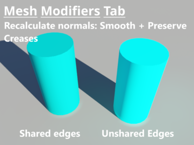
Smooth + preserve creases: Similar to "Conservative update" except that it preprocesses the model to merge any duplicate normals. After doing this it recalculates each normal using the average of the normals of the faces that use the normal.
Benefits:- Preserves creases where edges used per-face normals in the original model.
Drawbacks:
- Cannot create normals where they didn't previously exist.
-
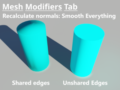
Smooth everything: All the prior normals are cleared. A new normal is created for every vertex. Each normal is the average of the normals of the faces that use the vertex, therefore it creates a smooth appearance across faces that share vertices with other faces.
Benefits:- This works with models that didn't define any normals before.
Drawbacks:
- Does not produce sharp edges unless the faces use separate vertices.


Surface Shaders Tab[edit]

Description: This tab lets you assign a surface shader to texture the object. If there was a .mtl file associated with the OBJ file, a Parts Shader with its associated nodes will be created and assigned to the Surface shader input.
Settings:
- Surface shader: Use this parameter to assign a surface shader to the object.
- Displacement tolerance If you find that rough or spikey surfaces are showing problems at bucket edges, for example spikes having cut off tops, or gaps in ray traced shadows then increasing this value may help. However this can greatly increase render times. Relatively flat surfaces may render more quickly with smaller values. The default value is 1. However this is an advanced setting and you should not change it unless you have specific problem you need to address. If you are having problems try starting with 2 and then increase it by small increments until they're resolved. A value of 4 would be considered a high value.
- Smooth polygons at terminator: This fixes self-shadow artifacts at the lighting terminator of polygonal objects where the smooth normals are inconsistent with the geometric normal. This parameter is enabled by default.
- Darken bumps at terminator: This parameter approximates self-shadow of bump maps at the lighting terminator to reduce the chance of seeing a sharp line where the surface falls into shadow. This parameter is enabled by default.


Rendering Tab[edit]

Settings:
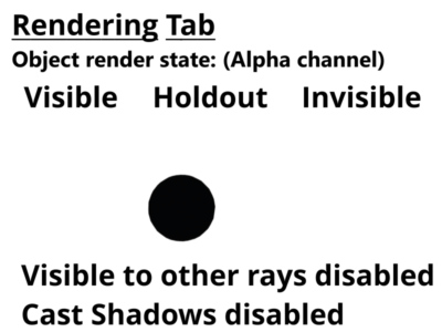
- Render mode: An object's render state can be set to “Visible”, “Invisible” or “Holdout”.
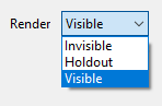
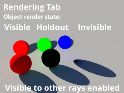
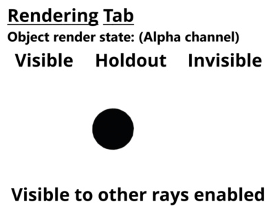
- When set to “Holdout”, an object is visible in the rendered image as a black shape with an alpha value of zero. When using render layers the object's render state is combined with the group visibility parameter to determine its least visible setting. "Invisible" is less visible than "Holdout", which is less visible than "Visible".
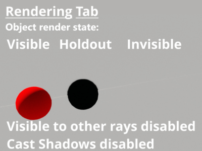
- Visible to other rays: When enabled, the object will be taken into account by all the rays determined by the renderer including those from the camera, direct and indirect lighting, etc. In the example below, a 100% reflective 3D object has been placed behind three coloured spheres in order to mirror the effect of the calculated rays.
- Cast shadows: This should be checked if you want the object to cast shadows.
- Double-sided surface: If this is checked object surfaces are double sided. A single sided surface is only visible from the "front", which is the direction the surface normal is pointing. If you look at it from the other direction the surface isn't visible. Double sided surfaces are visible from all directions.
- Use smooth normals: If this is checked the object normals are interpolated to make the surface appear smooth. If it's unchecked the surface will look faceted.
- Flip normals: Check this to flip or reverse the object normals. You might want to use this on an imported object if it has gaps or strange dark patches when rendered.
- Render method This popup has three options.
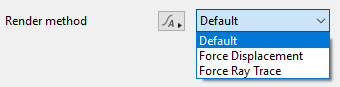
- Default: Ray Tracing is the default rendering method for an object. Typically it results in higher quality and faster rendering. When displacement is applied to a 3D object the render method should be changed to Force Displacement. When the object's render method is set to "Default", the object is rendered according to the Ray trace objects setting in the render node.
- Force Displacement: When enabled for the object, its surfaces will be subdivided into micropolygons at render time, which allows the 3D geometry to be displaced correctly but at the expense of slightly longer render times. It is useful when you have some objects you want to render with displacement but you don't want to change how all the rest of your objects are rendered, i.e. Ray traced.
- Force Ray Trace: When enabled for the object, its surfaces will be ray traced at render time, even if “Ray trace objects” is disabled in the Renderer settings. This can be useful when “Ray trace objects” is disabled in the Renderer in order for other 3D objects to use displacement, but you want this object to use Ray tracing for the highest quality rendering and it has not been displaced.
- Sorting bias (metres) This parameter gives you control over the order in which objects are rendered when using the micropolygon renderer. This does not apply to objects being rendered with the ray tracer. A large positive value, e.g. 10,000,000 (or 1e7) will usually force the object to render first. A large negative value, e.g. -10,000,000 (or -1e7) will usually force the object to render last, or after the terrain. This can be useful when rendering large objects with displacement, such as a lake object that lies mostly below the displaced terrain. By setting the lake object’s sorting bias value to something like -10,000,000 forces it to render after the terrain.

 |
 |
 |
 |
 |
 |


Transform Tab[edit]

Settings:
- Translate: This sets the position of the object.
- Rotate: This rotates the object about its origin. The order of the values is heading, pitch then bank.
- Scale: You can use this parameter to scale the object in the X, Y and Z directions.
Angular Position Tab[edit]

Description: This tab has settings which use angles and distance to set the position of the rock relative to the scene origin. These settings are an alternative to using the Translate setting in the Transform tab. The diagram below shows how all the parameters relate to each other and the origin.

Settings:
- Heading: This angle sets the rotation of the object around the scene origin, in the XY plane, increasing as you turn clockwise.
- Elevation: This angle sets the vertical part of the position. You could think of it as the angle above or below the horizon. 90 is straight up, -90 is straight down.
- Distance: This sets the distance from the origin, in metres.
Import Tab[edit]

Description: These parameters apply to .chan/.mov and FBX import.
Settings:
- Import offset: This setting allows you to offset the positions imported from the file. As an example, you might want the positions imported from the file to be moved 10 metres in the X direction. To do that enter 10 for the X coordinate and import the file.
- Import scale: You can use this setting to scale values imported from the file.
- Import Chan file: This param specifies the file to be imported. When you a choose a new file you will be prompted to import the file. If you choose not to import it immediately you can click the Import chan File button to perform the import.
The bounding box is a box which surrounds (or bounds) an object or shader. This box shows the maximum extents of the item inside it. Sometimes abbreviated as "b-box".
A parameter is an individual setting in a node parameter view which controls some aspect of the node.
A shader is a program or set of instructions used in 3D computer graphics to determine the final surface properties of an object or image. This can include arbitrarily complex descriptions of light absorption and diffusion, texture mapping, reflection and refraction, shadowing, surface displacement and post-processing effects. In Terragen 2 shaders are used to construct and modify almost every element of a scene.
Literally, to change the position of something. In graphics terminology to displace a surface is to modify its geometric (3D) structure using reference data of some kind. For example, a grayscale image might be taken as input, with black areas indicating no displacement of the surface, and white indicating maximum displacement. In Terragen 2 displacement is used to create all terrain by taking heightfield or procedural data as input and using it to displace the normally flat sphere of the planet.
When Terragen renders, it divides the image up into buckets or tiles. Each bucket is rendered separately, allowing multiple buckets to be rendered at once. It also allows memory to be used more efficiently.
Literally, to change the position of something. In graphics terminology to displace a surface is to modify its geometric (3D) structure using reference data of some kind. For example, a grayscale image might be taken as input, with black areas indicating no displacement of the surface, and white indicating maximum displacement. In Terragen 2 displacement is used to create all terrain by taking heightfield or procedural data as input and using it to displace the normally flat sphere of the planet.
A single object or device in the node network which generates or modifies data and may accept input data or create output data or both, depending on its function. Nodes usually have their own settings which control the data they create or how they modify data passing through them. Nodes are connected together in a network to perform work in a network-based user interface. In Terragen 2 nodes are connected together to describe a scene.