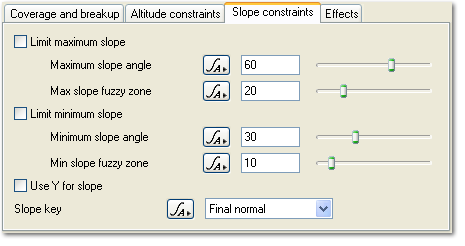
Surface Layer - Slope Constraints Tab
Description:
The Slope Constraints tab has settings which let you control where your surface layer appears according to slope. You can use these settings to make the layer only appear on flatter parts of your scene, steeper parts of the scene or somewhere in between.
Let's say you want to add a green layer for distant grass. Grass typically only grows on areas with a slope less than 45° so you can use the maximum slope constraint to prevent it appearing on areas steeper than that.
You can use the 3D Preview to help you find angles to use for slope constraints. Imagine you have an area of terrain which is gently rising and then turns into a cliff. You want your surface layer to appear everywhere except on the cliff. You can do that like this:
- Navigate in the 3D Preview so you can see the area of interest.
- Wait for the 3D Preview to refine to a reasonable detail level. The more it has refined the more accurate the next step will be. If you don't need it to be really accurate just let it go to a reasonable level.
- Now context click on the cliff face, near the point where your gently rising terrain turns into the cliff. In the context menu select the Copy Slope Angle item. This will copy the slope angle of the point in the scene where you clicked to the clipboard.
- Paste the copied angle into the text field of the Maximum slope angle parameter.
- Check the Limit maximum slope checkbox.
This will restrict your surface layer so it only appears in parts of the scene which are less steep than the cliff.
Settings:
- Limit maximum slope: Check this to turn on the maximum slope constraint. This will stop the surface layer appearing on areas steeper than the angle specified in the Maximum slope angle parameter.
-
Maximum slope angle: This setting controls the maximum slope the layer will appear at.
-
Max slope fuzzy zone: This controls the width of the fuzzy zone for the maximum slope constraint. The fuzzy zone is an area of the layer that is less steep than the maximum slope which gets blended with underlying layers. Fuzzy zones are explained in detail here.
-
Limit minimum slope: Check this to turn on the minimum slope constraint. This will stop the surface layer appearing on areas with less slope than the angle specified in the Minimum slope angle parameter.
-
Minimum slope angle: This setting controls the minimum slope the layer will appear at. It will not appear on areas flatter than this angle.
-
Min slope fuzzy zone: This controls the width of the fuzzy zone for the minimum slope constraint. The fuzzy zone is an area of the layer that is steeper than the minimum slope which gets blended with underlying layers. Fuzzy zones are explained in detail here.
-
Use Y for slope: (TBC) Slope is normally calculated based on the normal specified using the Slope key parameter below. This means that wherever you go on the planet/object slopes will stay the same relative to the surface. If you check this parameter then the Y value from the normal will be used instead which means the angle now becomes relative to the Y axis. As you move further from the planet origin the slope will change. This is most useful for creating global planet-wide effects. For normal surfacing situations you can ignore this setting.
-
Slope key: (TBC) This popup list lets you choose different aspects of the scene to take the slope angle from. It has the following options:
- Final normal: This is the final normal computed after all displacement has happened in the scene.
-
Terrain normal: This is the terrain normal, normally obtained from the last Compute Terrain node.
-
Planet/object normal: This the normal from the planet or object the surface layer is attached to, after displacement has been applied.
Back to: Surface Layer
Context clicking shows a contextual menu. On Windows this would normally be done with a right click. On OS X this could be a control-click or a right click.
A parameter is an individual setting in a node parameter view which controls some aspect of the node.
Literally, to change the position of something. In graphics terminology to displace a surface is to modify its geometric (3D) structure using reference data of some kind. For example, a grayscale image might be taken as input, with black areas indicating no displacement of the surface, and white indicating maximum displacement. In Terragen 2 displacement is used to create all terrain by taking heightfield or procedural data as input and using it to displace the normally flat sphere of the planet.
A single object or device in the node network which generates or modifies data and may accept input data or create output data or both, depending on its function. Nodes usually have their own settings which control the data they create or how they modify data passing through them. Nodes are connected together in a network to perform work in a network-based user interface. In Terragen 2 nodes are connected together to describe a scene.
