Render Node (TG4)
Contents
Overview[edit]
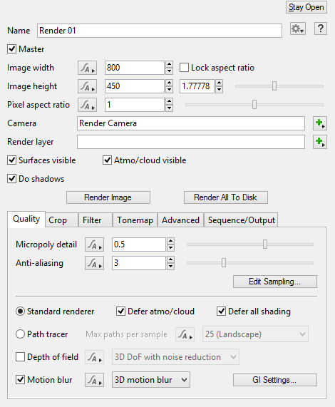
The Render node contains the settings used to produce final renders and can also be used to start rendering images and animation sequences. The Render node works in concert with the Camera node to create a render of your scene from a specific perspective.
Basic controls include the Width and Height of your output image, the camera from which your scene will be rendered, overall scene Detail, and Antialiasing. Many additional controls for fine-tuning scene detail and quality are also provided, including Global Illumination (GI) settings, as well as Contrast and Gamma Correction functions. You can also render partial crops of your select cameras view using the Crop Region functions. Sequence/Output allows you to output a sequence of images for animation (in versions of Terragen that include Animation features).
Settings
- Master: Check this to make the node the Master render node. The Master render node is the one which will be used to render projects loaded from the command line or a batch file.
- Image width: This param sets the width of the rendered image in pixels.
- Image height: This param sets the height of the rendered image in pixels.
- Lock aspect ratio: If this is checked then the image aspect ratio is locked. When you make changes to the image width or height the other param will be changed so that the aspect ratio of the image is maintained.
- Aspect ratio: You can change the aspect ratio for the image using the controls under the Lock aspect ratio param. Values greater than 1 will make the image wider and values less than 1 will make the image taller.
- Camera: This param sets the Camera node used for rendering the image. A Render node must have a camera assigned to it before it can render.
- Render layer: Professional Edition only. This may be assigned a Render Layer node for advanced control over the contents of the scene and the output images. For more information refer to Render Layers and Render Elements.
- Surfaces visible: If this is unchecked then surfaces (e.g. terrain, vegetation etc.) are rendered as "holdouts". This means they will appear to the camera as if they were black and will have a value of 0 in the alpha channel of the rendered image.
- Atmo/cloud visible: If this is unchecked then the atmosphere and clouds will not be directly visible to the camera. It will appear as though there is no atmosphere, but the atmosphere may still affect the lighting of the scene.
- Do shadows: Uncheck this to stop shadows rendering.
- Render Image: Clicking this button will start rendering an image. If you want an image to be automatically saved to disk when the render finishes, use "Render All To Disk" instead.
- Render All To Disk: Clicking this button will start rendering an image, and when it finished it will save the image to the path and filename specified on the Sequence/Output tab. If "Extra output images" is enabled on the Sequence/Output tab it will also save any render elements that are enabled.
Quality Tab[edit]
Settings
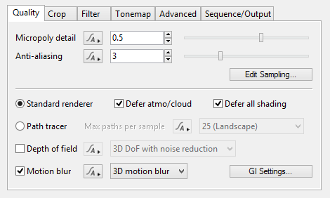
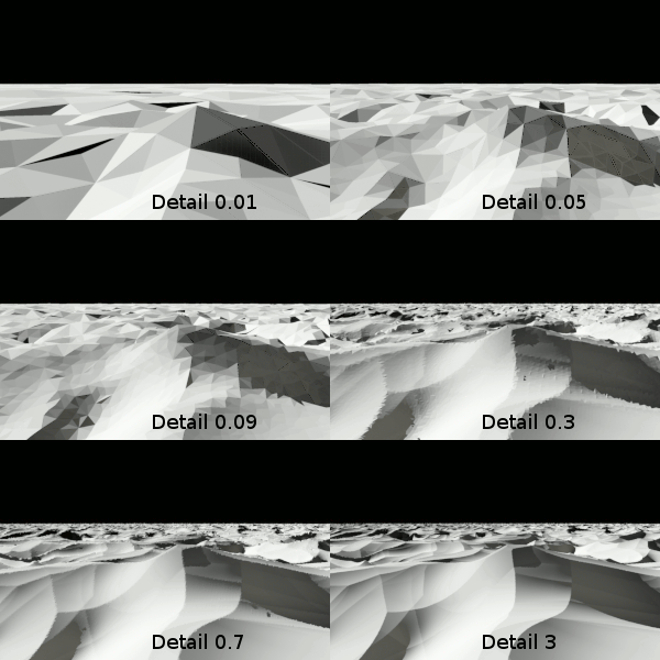
- Detail / Micropoly detail: This setting controls the size of the micro-polygons that surfaces are divided up into when rendering. Higher values provide more detail by using smaller micro-polygons. Although you can enter any value here the normal range is from 0 to 1. A setting of 0.8 is high quality. Increasing this value can lead to longer render times.
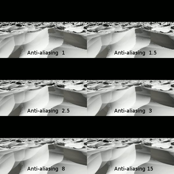
- Anti-aliasing: This controls the amount of anti-aliasing in the image. This is one of the most important settings for controlling the quality of your image and the time it takes to render. This parameter is also shown in the Render Pixel Sampler. The square of the anti-aliasing number tells you the maximum number of primary rays that are traced per pixel of the image, or in other words the maximum samples per pixel. An anti-aliasing value of 3 means that up to 9 samples can be taken per pixel; a value of 8 means that some pixels may take up to 64 samples, and this is usually enough for very good images. Adaptive sampling techniques are used to avoid taking the maximum number of samples where the sampler detects that the contrast between adjacent samples is below some threshold. This can be an effective way to concentrate anti-aliasing work where it is needed most, to increase quality and reduce the render time.
- Edit sampling…: Clicking this button opens the Render Pixel Sampler which lets you set advanced sampling parameters.
- Defer atmo/cloud: If this is checked the atmosphere is rendered using raytracing. This can give better looking results than the normal micropolygon renderer and might be faster. However it may be slower for some scenes. More info: Ray Trace Objects and Defer Atmosphere/Cloud.
Crop Tab[edit]
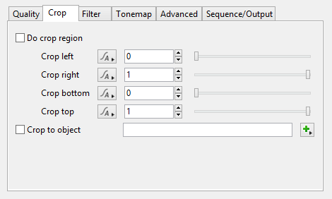
The settings on the Crop tab let you crop the rendering to a specific part of an image. Only parts of the scene inside the crop region are rendered. Using the crop region can be useful in several ways. You can use it to render just a small part of an image to preview it or check something. You can use it to re-render a specific part of an image. You could also use it to divide an image into several parts to be rendered on multiple machines, although it is better to use the tile options on the command line for this purpose.
The positions of the crop region edges are set as a proportion of image size, rather than by specifying the size in pixels. The position values run from 0 to 1. The top or left side of the image is 0. The right or bottom side of the image is 1. Let's say you want to render only the left half of an image. Set the top to 0 and the bottom to 1 to render the full height of the image. Now set the left to 0 and the right to 0.5. 0.5 is halfway across the image.
An easier way to set the crop region edges is to use the 3D Preview. When you check Do crop region the crop region is drawn in red on the 3D Preview. You can click and drag to resize the crop region in the preview.
Settings
- Do crop region: If this is checked the render will be cropped specified in the fields below.
- Crop left: This sets the position of the left side of the crop region.
- Crop right: This sets the position of the right side of the crop region.
- Crop bottom: This sets the position of the bottom side of the crop region.
- Crop top: This sets the position of the top side of the crop region.
- Crop to object: If this is checked the render will be cropped to the bounding box of the assigned object. Please note that the object must be TG's built-in Sphere object. If you use some other sort of object the render won't be cropped.
Filter Tab[edit]
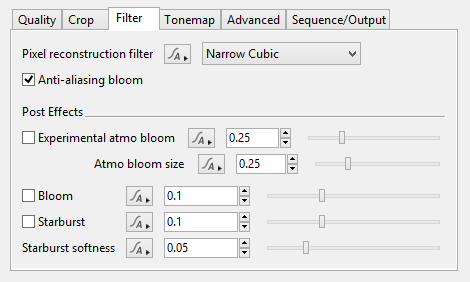
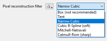
- Pixel reconstruction filter: This pop-up menu has six options in which to specify the algorithm used to convert the image samples into pixel values.
- Anti-aliasing bloom: This setting reduces the aliasing of pixels that are too bright to be handled by normal anti-aliasing techniques. It uses a combination of pixel and subpixel convolutions. Very bright points and edges appear to expand and are slightly softened with this option enabled.
Post Effects section[edit]
The optical effects settings below are applied to the rendered image. As such, they are unaware of the shaders used to create those pixels, and therefore do not change according to the luminance.
- Experimental atmo bloom: This post process affects only the atmosphere and clouds.
- Atmo bloom size: When the Experimental atmo bloom setting is checked, this setting controls the spread of the bloom effect.
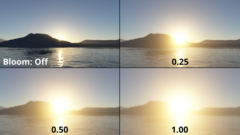
- Bloom: This setting simulates a small amount of diffusion by the lens and other reflections within the camera. To enable the bloom effect, make sure to click the checkbox A value of 0.1 gives a slightly stronger effect than you’d see with most cameras. Bloom can be created by the sun, brightly lit objects and clouds, luminance, reflections and highlights, etc. It is most noticeable when pixel values are very bright, or they cover a large enough area of the image so that they add up to a lot of light. Surfaces with a luminous value of 1 aren’t very bright, so you may need to increase the surfaces’ luminous value to see the bloom effect on it.
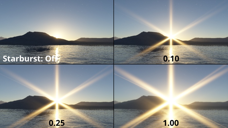
- Starburst: When checked, a starburst effect is added to the rendered image. Increasing the value increases the intensity of the starburst effect.
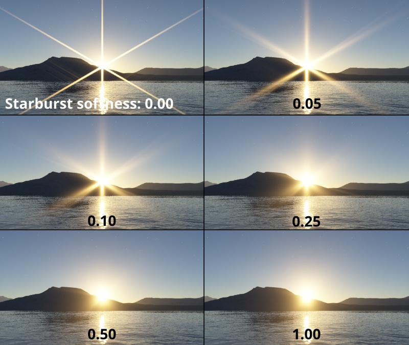
- Starburst softness: When the Starburst setting is checked, this setting controls the softness of the starburst. Higher values soften and diffuse the starburst effect.
Tonemap Tab[edit]
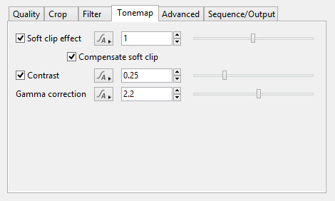
- Soft clip effect: When checked, this setting alters the brightness of pixels to improve the appearance of very bright objects in the image, giving a result more similar to photographic film than traditional 2D graphics. Areas of the image which would otherwise be much brighter than white are brought into the visible range so that details can be seen, and it avoids hard boundaries around bright halos. The effects of this setting are not applied to EXR or other HDR formats, they are only applied when saving low dynamic range formats such as BMP and TIFF or when viewing the rendered image on the monitor.
- Compensate soft clip: Description coming soon.
- Contrast: Description coming soon.
- Gamma correction: This setting raises the value “to the power of” the value (or the inverse of the gamma value).
- Using OCIO for tonemap and display: Description coming soon.
Advanced Tab[edit]
The Advanced Tab holds some advanced settings for managing the rendering process. There are settings related to the number of threads used during a render, certain blocks of memory used during rendering and how some render information is generated.
Managing render threads
Terragen can render different sections of the image at the same time. These image sections are known as buckets. Many computers have multiple processor cores, and on these computers rendering can be completed faster if each core renders a bucket at the same time. The buckets are assigned to render threads. A thread is a section of a computer program which can do work at the same time as other parts of a program.
When Terragen starts up it automatically detects the number of cores your computer has. This number is displayed on the Splash Screen. By default Terragen creates one render thread for each core it detects. For example, if your computer has 4 cores then Terragen will create 4 render threads during rendering. This means Terragen can render 4 buckets at the same time. It is possible to override the core detection in the Startup panel of the preferences.
The render node gives you control over this on a per project, per render node basis. You can use the Maximum threads parameter to limit how many render threads Terragen creates for this particular render node. This parameter set the upper limit on the number of render threads created.
Let's say your computer has 8 cores and you only want it to use 4 cores for some reason. To do this you would set the Maximum threads parameter to 4.
Caution: If you think you might want to share your project files with other people, be aware that limiting the threads in this way could make the render much slower than it needs to be on other people's computers. The safest choice is to leave this at the default value of 64 and to set an override in Preferences > Startup instead.
Settings
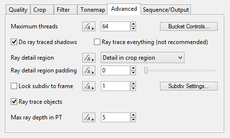
- Maximum threads: Sets the maximum number of threads Terragen creates during rendering.
- Ray trace everything (not recommended): This is explained here: Ray Trace Objects and Defer Atmosphere/Cloud.
- Ray detail region: The ray detail region is the area in the scene where polygons with displacement are fully subdivided by the ray tracer. Polygons outside this area are only coarsely subdivided. Sometimes you might have problems like shadows cast by objects outside the the camera view not seeming accurate. This could be corrected by changing the ray detail region.
- No detail: Nothing is fully subdivided. Everything is subdivided only coarsely.
- Detail in crop region: Areas within the camera view - or the crop region if it's enabled - are fully subdivided by the ray tracer. Areas outside this are only coarsely subdivided.
- Detail in camera: Areas within the camera view are fully subdivided by the ray tracer. Areas outside this are only coarsely subdivided.
- 360 degree detail (optimal): The subdivision detail is highest in the direction that the camera is looking towards. The detail gradually decreases to 33% of the highest detail behind the camera, so detail outside of the camera view is usually higher than in the previous two modes. In this mode Ray detail region padding is ignored. This mode does not work with orthographic cameras.
- 360 degree detail (highest): The subdivision detail is uniform in all directions around the camera position, even behind the camera. This produces the highest all-round detail in displacements that cast shadows or appear in ray traced reflections, but beware that this mode can increase render times greatly, especially if there are any ray traced reflections appearing on objects with high curvature or displacement. In most cases it's preferable to use 360 degree detail (optimal) instead. In this mode Ray detail region padding is ignored. This mode does not work with orthographic cameras.
- Ray detail region padding: If you are using Detail in crop region or Detail in camera you can use this "padding" amount to enlarge the ray detail region beyond the crop region or camera view. The value is typically between 0 and 1 and it controls the amount of padding. 0 means no padding. 1 adds a border around that area which is the same as the width or height of the area. This will make the ray detail region 3 times as wide and 3 times as tall (as seen from the camera). If you need to go higher than 1, consider changing the Ray detail region to 360 degree detail (optimal).
- Lock subdiv to frame: This can be used to help prevent popping shadows in an animation by forcing the set of micropolygons that are used to cast shadows and reflections to be the same for every frame. The number to the right of the checkbox is the frame of animation that you want to lock to. You should choose a frame number that you think best represents the view of the terrain that will be visible throughout the shot (for example the middle frame). When the checkbox is checked the renderer looks at where the camera is on that frame number and uses that camera to subdivide the terrain to generate the shadow-casting (and reflection-casting) micropolygons. Then for every frame the shadow/refection-casting polygons will be identical, eliminating one of the causes of popping shadows. However, it has some drawbacks. Firstly, the shadow detail is optimal only when the render is of a similar viewpoint to the frame being locked to. If you render parts of the terrain that aren't visible in the locked-to frame you may lose detail in the shadows or have large areas of false-positive or false-negative shadows, but this can often be mitigated by using the "ray detail region" and/or "ray detail region padding" settings. Secondly, if the camera moves a great distance away from its position on the locked-to frame the renderer might make suboptimal choices about the level of detail of the shadows. This can cause there to be too much detail in some areas (leading to longer render times) or too little detail in others (such as where the camera is closer to the terrain than it is on the locked frame).
- Subdiv Settings...: Clicking on this will open Render Subdiv Settings. This contains some advanced settings that affect the rendering of subdivisible, displaceable surfaces.
- Ray trace objects: If this is checked, objects (plants for example) are rendered using raytracing. Generally speaking this leads to a higher quality image which renders more quickly. The disadvantage to using raytracing is that objects will not be rendered with displacement. If an object has displacement mapping in its textures the raytracer will convert this to bump mapping. More info: Ray Trace Objects and Defer Atmosphere/Cloud
Sequence/Output Tab[edit]
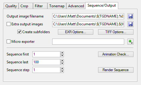
The Sequence/Output Tab contains settings which relate to the images and geometry output during rendering, as well as allowing you to render animation sequences in versions of Terragen that include animation features.
Settings
- Output image filename: This is the filename of the main image that is saved to disk when you use "Render All To Disk", "Render Sequence" or render from a command line. This may be overridden on the command line (using the -o command), but if it isn't overridden then Terragen will use this filename. If you are using a render farm or render manager it might override this filename.
- Extra output images: The checkbox enables the output of additional Render Elements, or, if no render elements are rendered it outputs an alpha image. This applies when using "Render All To Disk", "Render Sequence" or rendering from a command line. This may be overridden on the command line (using the -ox command), but if it isn't overridden then Terragen will use this filename. If you are using a render farm or render manager it might override this filename. The word 'IMAGETYPE' (not including quotes) needs to be included somewhere in the filename if you want each render element to have a distinct filename. 'IMAGETYPE' is replaced by a word that represents the name of the render element. A list of these element names can be found here.
- Micro exporter: Check this param and assign a micro exporter node to export rendered scene geometry.
- Sequence first: Set the first frame rendered in an animation sequence.
- Sequence last: Set the last frame rendered in an animation sequence.
- Sequence step: Sets the step between frames in animation sequence. For example if you want to render every fifth frame in a sequence set this to 5.
- Render sequence: Click this button to start rendering an animation sequence.
Render Output Variables (build 4.4.18 and above)
"Output image filename" and "Extra output image filename" can use variables to generate filenames dynamically. When an image is rendered and saved to disk, the actual filename may depend on any variables that you include in the filename field. For example, the default output filename is "${TGDNAME}.%04d.tif". When an image is rendered and saved, the actual filename written to disk depends on the name of the project file (TGD file) and the current frame number, e.g. "Untitled.0001.tif".
The following variables can be used anywhere in the filename field:
- ${BUILDNUMBER} // e.g. 4.4.18.1
- ${CAMERA} // the name of the camera at the moment the frame started rendering
- ${IMAGETYPE} or IMAGETYPE // e.g. tgSurfDirect, tgCloudRgb etc. If used for the main output it will insert tgBeauty
- ${LAYER} or ${RENDERLAYER} // the name of the render layer at the moment the frame started rendering, if one was connected
- ${RENDER} or ${RENDERER} or ${RENDERNODE} // the name of the render node at the moment the frame started rendering
- ${RENDERSECONDS} // render time in seconds, e.g. 134
- ${RENDERTIME} // render time formatted with hours, minutes and seconds (e.g. 1h07m24s), or without the hours if shorter than 1 hour, e.g. 02m14s
- ${TGDNAME} // the name of the last saved or loaded TGD file at the moment the frame started rendering (or "Untitled"), without the path and without the extension
More Information[edit]
For more information on how Terragen renders a scene, review the Rendering Methods page.
A single object or device in the node network which generates or modifies data and may accept input data or create output data or both, depending on its function. Nodes usually have their own settings which control the data they create or how they modify data passing through them. Nodes are connected together in a network to perform work in a network-based user interface. In Terragen 2 nodes are connected together to describe a scene.
A parameter is an individual setting in a node parameter view which controls some aspect of the node.
A single element of an image which describes values for color and/or intensity, depending on the color system which the image uses. Groups of ordered pixels together form a raster image.
The bounding box is a box which surrounds (or bounds) an object or shader. This box shows the maximum extents of the item inside it. Sometimes abbreviated as "b-box".
This is essentially the brightness of the colour. Terragen converts RGB colours to greyscale by taking the luminance of the colour.
When Terragen renders, it divides the image up into buckets or tiles. Each bucket is rendered separately, allowing multiple buckets to be rendered at once. It also allows memory to be used more efficiently.
Literally, to change the position of something. In graphics terminology to displace a surface is to modify its geometric (3D) structure using reference data of some kind. For example, a grayscale image might be taken as input, with black areas indicating no displacement of the surface, and white indicating maximum displacement. In Terragen 2 displacement is used to create all terrain by taking heightfield or procedural data as input and using it to displace the normally flat sphere of the planet.
