Planet
Contents
Overview[edit]
The Planet object is the basis for most scenes in Terragen. It consists of the terrain geometry, surface attributes, and the atmosphere created around it. When a new Planet node is added to a project, a Power Fractal Shader v3 node is assigned to its Surface shader, and a Planet Atmosphere node is assigned to its Atmosphere shader, within its internal node network. Although Terragen can zoom from all the way out in space to a very close-up position on the planet surface, we recommend that if you’re creating project with a localized scale, as opposed to a planetary scale, that you create the scene around the origin of the planet, which is effectively the North Pole by default. As you move long distances from the origin, the coordinates begin to lose accuracy and you might start to see things you're not expecting. For example, if you want to model a real world location, such as the South Island of New Zealand, it’s actually not a good idea to put that geometry in the same place it would exist in the real world. Rather, the geometry that makes up the South Island of New Zealand should be positioned at the North Pole. Designing your project around the origin helps to ensure the accuracy of your scene. Terragen makes it easy to shift georeferenced data to the origin of the project, by entering the latitude and longitude coordinates in the Planet origin settings. It’s a bit like spinning the whole planet around so that the area you’re interested in ends up at the North Pole.
You can have multiple planets in a project. For example, to create the Moon you can add a new Planet object, then position and size it appropriately. Here are the sizes of the heavenly bodies in our solar system:
- The Moon: 1,738,000 m
- Mercury: 2,439,000 m
- Venus: 6,052,000 m
- Earth (default planet size): 6,378,000 m
- Mars: 3,397,000 m
- Jupiter: 71,490,000 m
- Saturn: 60,268,000 m
- Uranus: 25,590,000 m
- Neptune: 25,629,000 m
- Pluto: 1,160,000 m
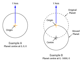
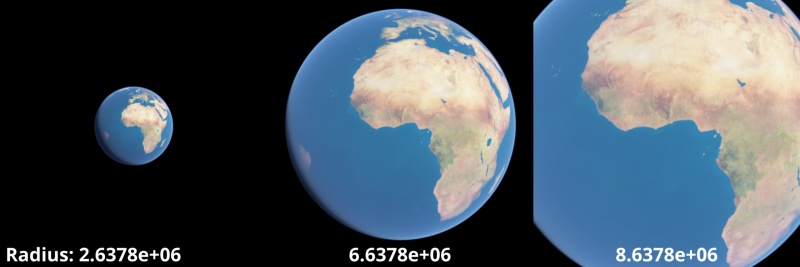
Changing the size of the planet requires the understanding of how the scene origin and the planet’s Centre and Radius settings are related to each other. Imagine that you want to create a small planet with a radius of 5,000 metres. If the planet’s Centre values were at the scene origin of 0,0,0 then the North Pole would end up 5,000 metres away from the origin. See Example A below.
To place the origin at the North Pole, we need to offset the position of the planet by setting the Y coordinate of the Centre setting to the same value of the Radiu, but make the value negative. For example, -5,000 metres. This translates the planet downwards on the Y axis and aligns the scene origin with the planet surface at the North Pole. See Example B below.
The easiest way to change the radius of the default planet, is to set the Radius parameter to the desired value then copy and paste that value into the Centre Y coordinate and make it negative.
Settings:
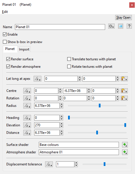
- Name: This setting allows you to apply a descriptive name to the node, which can be helpful when using multiple Planet nodes in a project.
- Enable: When checked, the node is active and the settings below will affect the surface. When unchecked, the node is ignored.
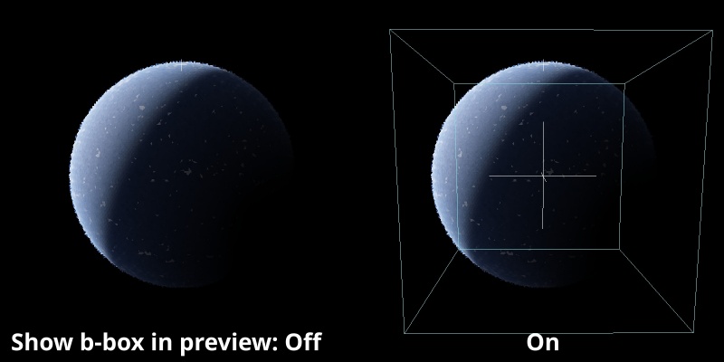
- Show b-box in preview: When checked, a bounding box will be displayed in the 3D Preview around the planet.
Planet Tab[edit]
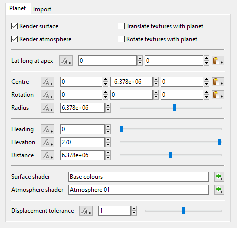
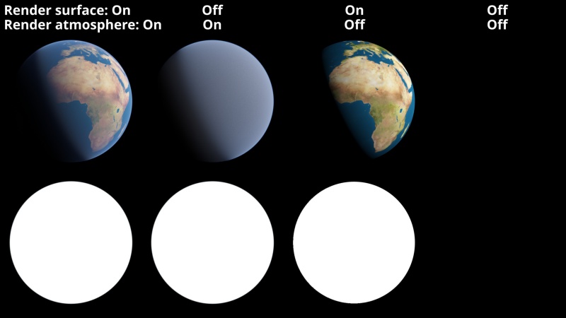
- Render surface: When checked, the surface of the planet is rendered using the shader or function nodes assigned to the Surface shader input. When unchecked, the surface is treated as invisible.
- Render atmosphere: When checked, the atmosphere of the planet is rendered using the shader or function nodes assigned to the Atmosphere shader input.
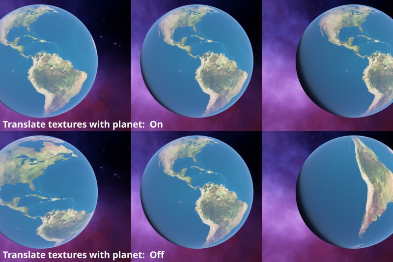
- Translate textures with planet: When checked, the textures of the planet will move with the planet as it is repositioned via its Centre settings. When unchecked, as the planet is translated it will seem to move through its textures.
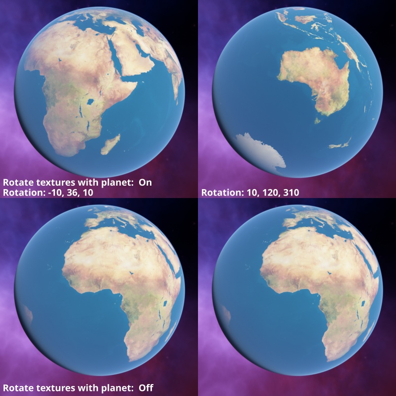
- Rotate textures with planet: When checked, the textures of the planet will rotate along with the planet as it is rotated via its Rotation settings. When unchecked, the textures do not rotate but remain fixed even though the planet geometry rotates.
- Lat long at apex: This setting controls the latitude and longitude at the apex or origin of the planet. By default this is set to 0,0 which corresponds to the North Pole on Earth. As mentioned above coordinate accuracy can get worse as you move away from apex. If you are using georeferenced data you can use an appropriate latitude and longitude to remap your area of interest to the scene origin which will help to avoid accuracy problems.
- Centre: This sets the position of the centre of the planet and by default is based on an Earth sized planet. Scientific notation is used to represent distances as they are often very large.
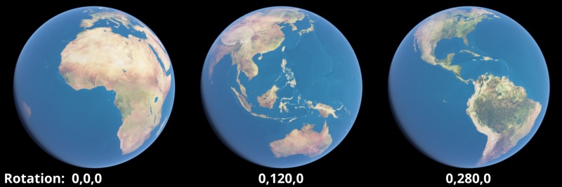
- Rotation: This setting controls the rotation of the planet about its centre.
- Radius: This setting determines the radius of the planet. By default it's set to the Earth’s radius in metres, i.e. 6,378 km. Scientific notation may be used to represent very large distances.
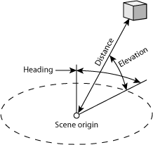
- Heading: This setting controls the position of the planet, in the XY plane. As the value is increased the planet rotates in a clockwise arc around the scene origin. Its distance from the origin is determined by the Distance setting below.
- Elevation: This setting controls the angle above or below the horizon where the planet will be positioned. , where 90 degrees is straight up and -90 degrees is straight down. It is the Y axis, or vertical part, of the position.
- Distance: This setting controls the distance of the planet from the scene origin, in metres.
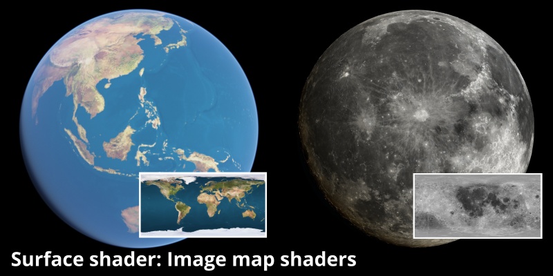
- Surface shader: The shader or function nodes assigned to this setting determine the look of the planet surface. Typically this is the last node in the workflow starting with the Terrain group and culminating in the Shader group.
- Atmosphere shader: The shader or function nodes assigned to this setting determine the look of the atmosphere. Typically this is the last node in the workflow within the Atmosphere group and comprises the atmosphere node and any cloud layers.
- Displacement tolerance: If you find that rough or spikey surfaces are showing problems at bucket edges, for example spikes having cut off tops, or gaps in ray traced shadows then increasing this value may help. However this can greatly increase render times. Relatively flat surfaces may render more quickly with smaller values. The default value is 1. However this is an advanced setting and you should not change it unless you have specific problems you need to address. If you are having problems try starting with 2 and then increase it by small increments until they're resolved. A value of 4 would be considered a high value.
Import Tab[edit]
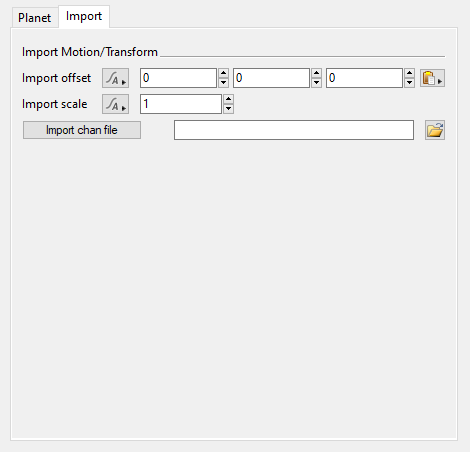
These parameters apply to .chan/.mov and FBX import.
- Import offset: This setting allows you to offset the positions imported from the file. As an example, you might want the positions imported from the file to be moved 10 metres in the X direction. To do that enter 10 for the X coordinate and import the file.
- Import scale: You can use this setting to scale the values imported from the file.
- Import chan file: This setting specifies the file to be imported. When you choose a new file you will be prompted to import the file. If you choose not to import it immediately you can click the Import chan File button to perform the import later on.
A shader is a program or set of instructions used in 3D computer graphics to determine the final surface properties of an object or image. This can include arbitrarily complex descriptions of light absorption and diffusion, texture mapping, reflection and refraction, shadowing, surface displacement and post-processing effects. In Terragen 2 shaders are used to construct and modify almost every element of a scene.
A parameter is an individual setting in a node parameter view which controls some aspect of the node.
A single object or device in the node network which generates or modifies data and may accept input data or create output data or both, depending on its function. Nodes usually have their own settings which control the data they create or how they modify data passing through them. Nodes are connected together in a network to perform work in a network-based user interface. In Terragen 2 nodes are connected together to describe a scene.
The bounding box is a box which surrounds (or bounds) an object or shader. This box shows the maximum extents of the item inside it. Sometimes abbreviated as "b-box".
When Terragen renders, it divides the image up into buckets or tiles. Each bucket is rendered separately, allowing multiple buckets to be rendered at once. It also allows memory to be used more efficiently.
