Plane
Overview[edit]
The Plane node creates a single sided flat plane object, which is visible only from the “front”, that is to say, when viewed from behind the plane will not be seen. By default the plane is rectangular, but it can be sheared so that its shape becomes a parallelogram. The plane can be textured just like any other object, and can also be displaced.
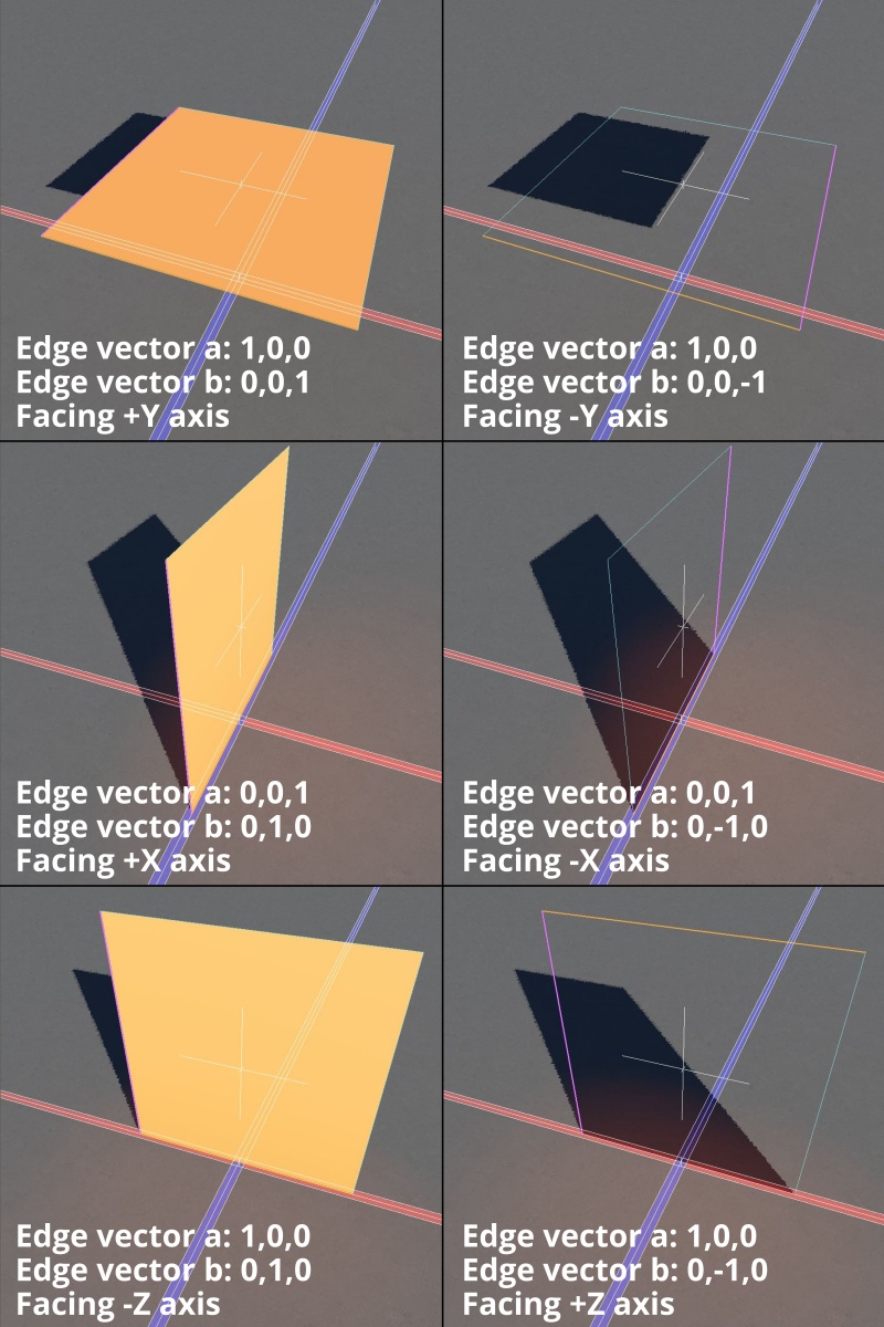
In order to help you size and orient the plane in the 3D Preview pane, the plane object’s A edge is drawn in orange and its B edge is drawn in magenta, while its other two edges are drawn as dashed lines to complete the bounding box. If you can see the edges of the plane in the preview, but not the plane itself, then you’re viewing the plane from “behind”.
You orient the plane by setting the direction of two of its edges, using the Edge vector a and Edge vector b parameters. By pointing those edges in the desired direction you control the way the plane faces.
Below are some common orientations of the plane object.
Settings:
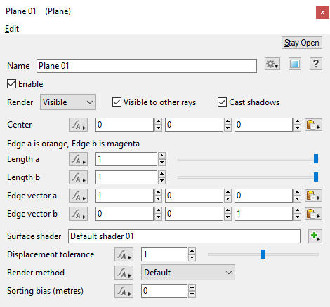
- Name: This setting allows you to apply a descriptive name to the node, which can be helpful when using multiple Plane nodes in a project.
- Enable: When checked, the node is active and the Plane object will appear in the scene with the settings below applied to its surface. When unchecked, the node is ignored.
- Render: An object's render state can be set to Visible, Invisible or Holdout. When set to Holdout, an object is visible in the rendered image as a black shape with an alpha value of zero. When using render layers the object's render state is combined with the group visibility parameter to determine its least visible setting. Invisible is less visible than Holdout, which is less visible than Visible.
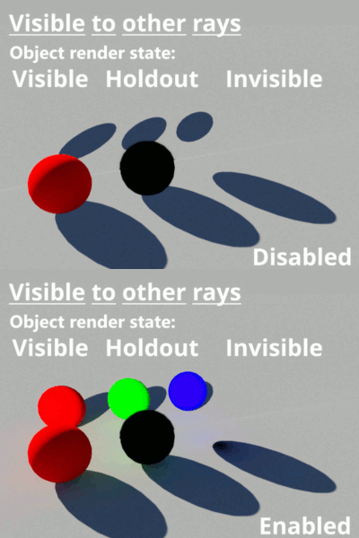
- Visible to other rays: When enabled, the plane object will be taken into account by all the rays determined by the renderer including those from the camera, direct and indirect lighting, etc. In the example below, a 100% reflective 3D object has been placed behind three coloured spheres in order to mirror the effect of the calculated rays.
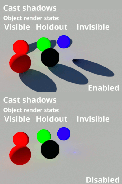
- Cast shadow: When checked, the plane object will cast shadows.
- Center: This setting defines the position of the centre of the plane object.
- Length a: This setting defines the length, in metres, of the orange coloured A edge.
- Length b: This setting defines the length, in metres, of the magenta coloured B edge.
- Edge vector a: This setting defines the direction of the orange coloured A edge. A value of 1 in any of the axis input boxes means that the edge is fully pointing along that axis. Values less than 1 mean that the edge is pointing in a percentage of that direction along that axis. When the two edge vectors are at right angles to each other the plane will be rectangular. You can shear the plane into a parallelogram shape by changing the edge vectors so that they are no longer at right angles.
- Edge vector b: This setting defines the direction of the magenta coloured B edge. A value of 1 in any of the axis input boxes means that the edge is fully pointing along that axis. Values less than 1 mean that the edge is pointing in a percentage of that direction along that axis. When the two edge vectors are at right angles to each other the plane will be rectangular. You can shear the plane into a parallelogram shape by changing the edge vectors so that they are no longer at right angles.
- Surface shader: Use this setting to assign a surface shader to the plane object. The surface of the plane object is displaceable.
- Displacement Tolerance: Displacement tolerance: If you find that rough or spikey surfaces are showing problems at bucket edges, for example spikes having cut off tops, or gaps in ray traced shadows then increasing this value may help. However this can greatly increase render times. Relatively flat surfaces may render more quickly with smaller values. The default value is 1. However this is an advanced setting and you should not change it unless you have specific problem you need to address. If you are having problems try starting with 2 and then increase it by small increments until they're resolved. A value of 4 would be considered a high value.
- Render method: This popup has three options.
Default: Ray Tracing is the default rendering method for an object. Typically it results in higher quality and faster rendering. When displacement is applied to a 3D object the render method should be changed to Force Displacement. When the object's render method is set to Default, the object is rendered according to the Ray trace objects setting in the render node.
Force Displacement: When enabled for the plane object, its surfaces will be subdivided into micropolygons at render time, which allows the 3D geometry to be displaced correctly but at the expense of slightly longer render times. It is useful when you have some objects you want to render with displacement but you don't want to change how all the rest of your objects are rendered, i.e. Ray traced.
Force Ray Trace: When enabled for the plane object, its surfaces will be ray traced at render time, even if Ray trace objects is disabled in the Renderer settings. This can be useful when Ray trace objects is disabled in the Renderer in order for other 3D objects to use displacement, but you want this object to use ray tracing for the highest quality rendering and it has not been displaced.
- Sorting bias (metres): This setting gives you control over the order in which objects are rendered when using the micropolygon renderer. This does not apply to objects being rendered with the ray tracer. A large positive value, e.g. 10,000,000 (or 1e7) will usually force the object to render first. A large negative value, e.g. -10,000,000 (or -1e7) will usually force the object to render last, or after the terrain. This can be useful when rendering large objects with displacement, such as a lake object that lies mostly below the displaced terrain. By setting the lake object’s Sorting bias (metres) value to something like -10,000,000 forces it to render after the terrain.
The bounding box is a box which surrounds (or bounds) an object or shader. This box shows the maximum extents of the item inside it. Sometimes abbreviated as "b-box".
A vector is a set of three scalars, normally representing X, Y and Z coordinates. It also commonly represents rotation, where the values are pitch, heading and bank.
A single object or device in the node network which generates or modifies data and may accept input data or create output data or both, depending on its function. Nodes usually have their own settings which control the data they create or how they modify data passing through them. Nodes are connected together in a network to perform work in a network-based user interface. In Terragen 2 nodes are connected together to describe a scene.
A parameter is an individual setting in a node parameter view which controls some aspect of the node.
A shader is a program or set of instructions used in 3D computer graphics to determine the final surface properties of an object or image. This can include arbitrarily complex descriptions of light absorption and diffusion, texture mapping, reflection and refraction, shadowing, surface displacement and post-processing effects. In Terragen 2 shaders are used to construct and modify almost every element of a scene.
When Terragen renders, it divides the image up into buckets or tiles. Each bucket is rendered separately, allowing multiple buckets to be rendered at once. It also allows memory to be used more efficiently.
Literally, to change the position of something. In graphics terminology to displace a surface is to modify its geometric (3D) structure using reference data of some kind. For example, a grayscale image might be taken as input, with black areas indicating no displacement of the surface, and white indicating maximum displacement. In Terragen 2 displacement is used to create all terrain by taking heightfield or procedural data as input and using it to displace the normally flat sphere of the planet.
