Heightfield Shader
Overview[edit]
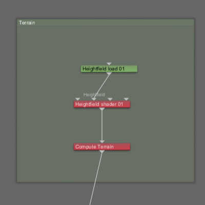
The Heightfield Shader is the basis for any heightfield terrain. It takes data from a heightfield operator, such as a Heightfield Generate node, and turns it into displacement. It is used to position the heightfield and control various aspects of its appearance. In addition, it can add fractal detail to the heightfield, which can greatly improve its appearance, especially if the heightfield is relatively low resolution.
Settings:
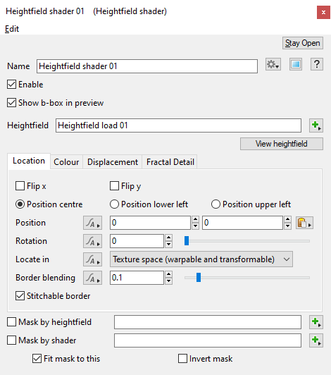
- Enable: When checked, the node is active and the settings below will affect the heightfield. When unchecked, the node and the heightfield operators feeding into it are ignored.
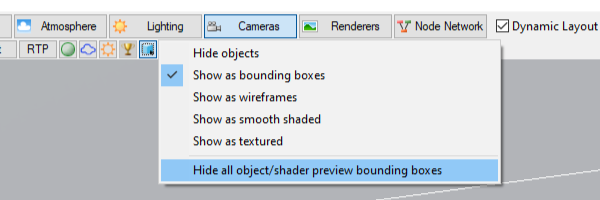
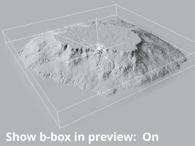
- Show b-box in preview: When checked and the 3D Preview display mode is not set to “Hide all object/shader preview bounding boxes”, a bounding box is drawn in the 3D Preview encompassing the area of the heightfield.
- Heightfield: The heightfield operator used to generate the heightfield data is assigned to this setting. For example, it could be a "Heightfield generator" or "Heightfield load" node.
- Mask by heightfield: When checked and a heightfield is assigned to this setting, the “weight” of its height values will act as a mask on the main heightfield assigned in the Heightfield setting. The highest point is given a weight value of 0 and the lowest a weight value of 1. Where a weight value of 0 is present no masking will occur and where a weight value of 1 exists full masking of the Heightfield shader’s colour and displacement are applied. The position and size of the heightfield assigned here does not matter because it is moved and scaled to fit the main heightfield.
- Mask by shader: When checked and shader or function nodes are assigned to this setting, the “weight” of their values act as a mask on the main heightfield assigned in the Heightfield setting. The largest value is given a weight value of 0 and the lowest value a weight value of 1. Where a weight value of 0 is present no masking will occur and where a weight value of 1 exists full masking of the Heightfield shaders colour and displacement are applied.
- Fit mask to this: When checked, the shader or function nodes assigned to the “Mask by shader” setting are given new texture coordinates in order to remap the unit square to the whole heightfield. The bottom left corner of the heightfield uses the blend shader at coordinates (0,0,0) and the top right corner of the heightfield uses the blend shader at coordinates (1,0,1). Note that not all shaders use texture coordinates so this setting may have no effect.
- Invert mask: When checked, the inverse of the shader or function nodes assigned as the mask is used as the mask.
Location Tab[edit]
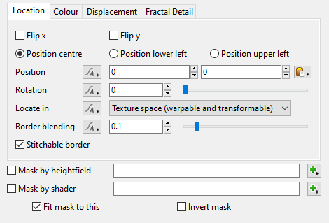
- Flip x: When checked, the heightfield is flipped along the X axis, that is the left becomes the right.
- Flip y: When checked, the heightfield is flipped along the Y axis, that is the top becomes the bottom.
- Position centre: When enabled, the heightfield is positioned at its center.
- Position lower left: When enabled, the heightfield is positioned using its lower left corner.
- Position upper left: When enabled, the heightfield is positioned using its upper left corner.
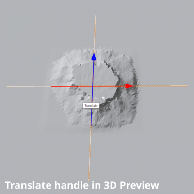
- Position: This setting allows you to reposition the heightfield, in metres, along the X and Z axis in 3D space. Note, this setting can also be manipulated by selecting the heightfield in the 3D Preview pane then clicking and dragging the translate handles.
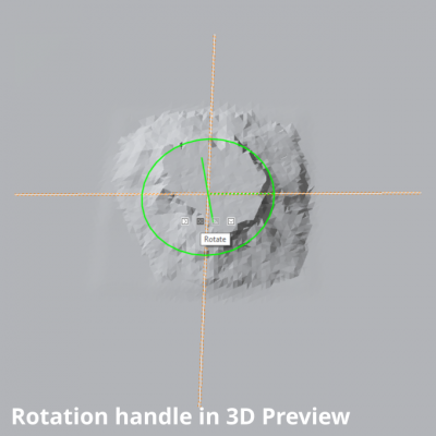
- Rotation: This setting allows you to rotate the heightfield in degrees. Note, this setting can also be manipulated by selecting the heightfield in the 3D Preview pane then clicking and dragging the rotation handle.
- Locate in:
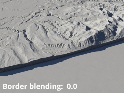
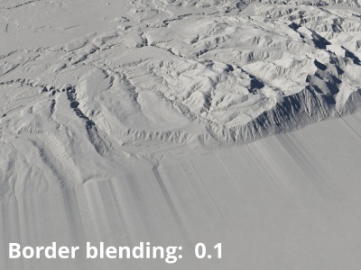
- Border blending: This setting controls how much of the heightfield is blended around its edges to smooth it into the surrounding terrain. The value ranges from 0 to 1. The value relates to the size of terrain. If you use 0 there is no blending performed and the heightfield will potentially have a hard edge all the way around it, like a vertical cliff. A value of 1 means that the heightfield will blend all the way across its width and height.
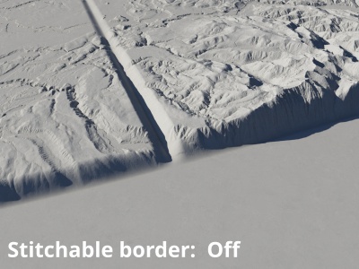
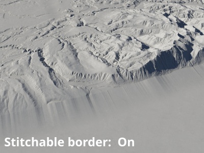
- Stitchable border: When checked, the blended border is extended outside the bounds of the heightfield. When “Flatten surface first” on the Displacement Tab is also checked, this will allow multiple heightfields to be aligned adjacent to one another without harsh seams between them.
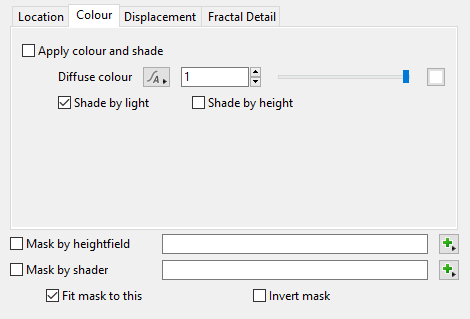
- Apply colour and shade: When checked, the shader will generate colour information. When unchecked, all settings on this tab are ignored.
- Diffuse colour: This setting controls the diffuse colour for the heightfield, and is also be affected by the “Shade by height” setting below. The diffuse colour may also be blended by the “Border blending”, “Blend by heightfield” and “Blend by shader” settings on the Location tab.
- Shade by light: When checked, the shader produces a standard Lambertian diffuse surface that is illuminated by the lights in the project. When unchecked, the shader will produce a luminous surface using the “Diffuse colour” value, and its diffuse colour output will be black (0). When using this shader as a blend shader or function for another shader then this setting should be checked so that the shader outputs the expected diffuse colour.
- Shade by height: When checked, the “Diffuse colour” is multiplied by a value depending on the heights of the heightfield. The lowest parts of the heightfield will be black (0) and the highest parts will be the diffuse colour, with other heights being some shade in between.
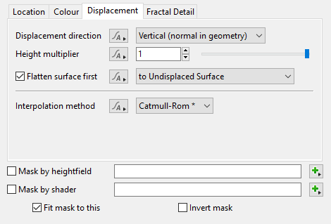
- Displacement direction: This popup menu has 3 options which let you choose the direction the displacement is applied in. Some options require a Compute Terrain or Compute Normal node to be connected somewhere above the Heightfield shader node in the workflow, in order to work properly.
- Height multiplier: This setting is used as a multiplier for the height values in the heightfield. The default value of 1 leaves the heights unchanged. A value of 2 will double the heights, while a value of 0.5 will make them half as high.
- Flatten out first: When checked, the planet surface beneath the heightfield is flattened prior to being displaced by the heightfield, and the displacement is treated as absolute Y position. This has the effect of replacing all prior input surface displacement with the displacement produced by the heightfield shader, and also eliminates the curvature of the planet. “Border blending”, “Blend by heightfield” and “Blend by shader” can affect the strength of these effects. When unchecked, the surface shader's displacement is additive, like most displacement shaders in Terragen. You may need to uncheck Flatten surface first if you want the heightfield to follow the curvature of the planet or if you are stitching adjacent heightfields with Stitchable border checked.
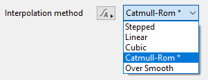
- Interpolation method: This setting provides a pop-up menu of five methods to control how the heightfield values are interpolated in between the actual height values. “Catmull-Rom” is the default method and is the best all round method.
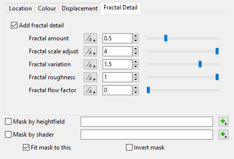
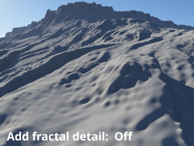
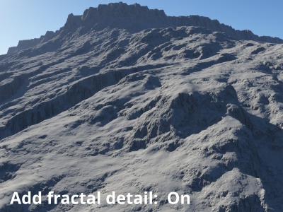
- Add fractal detail: When checked, fractal detail is added to the heightfield based on the setting values below.
- Fractal amount: This setting controls the overall amplitude, or strength, of the fractal detail added to the heightfield. Raising the value increases the roughness of the heightfield’s surface, while lowering the value makes the surface smoother.
- Fractal scale adjust: This setting controls the scale and amplitude of the noise patterns used to add fractal detail. The scale is measured in heightfield data points.
- Fractal variation: This setting controls the weight of the fractal detail’s internal feedback loop, which adds variation in strength at small scales.
- Fractal roughness: This controls the amount of emphasis on smaller scale details. The default value of 1 produces fractal detail which is “scale invariant” when considered as displacement. Larger values produce stronger small scale features, making the fractal appear rougher, while lower values produce lower amplitude small scale features, making the fractal appear smoother.
- Fractal flow factor: This setting controls the strength of a warping effect applied to the Fractal detail pattern, based on the surface normal of the heightfield data. This can give the impression that downhill flows as a result of erosion. High values may cause too much warping and look unrealistic.
Colour Tab[edit]
The Colour tab has settings that allow the shader to create colour information based on the heightfield. In the default project, you may notice that enabling the “Apply colour and shade” checkbox does not simply allow colour and shading to show up in the 3D Preview. This is most likely due to the location of the node in the workflow. By default, the node is located in the Terrain group, and further down the workflow, a Base colours node is overwriting the colour and shading changes from the Heightfield shader. In order for the Heightfield’s colour and shading to be seen, you’ll need to connect the Heightfield shader’s output to the input of a shader that accepts colour input, such as the Colour function input of a Surface Layer shader.
Displacement Tab[edit]
The Displacement tab controls how the values from the node connected to the Heightfield parameter are turned into displacement.
Vertical (normal in geometry): Displacement happens along the normal of the underlying planet or 3D object.
Normal: Displacement happens along the current surface normal.
Y axis: Displacement only happens along the normal of the underlying planet or 3D object. The displacement is scaled by the difference between the object normal and the surface normal. Displacement is reduced as the angle between the normals approaches 90°.
To Undisplaced Surface:
To computed terrain (pos. In texture):
To Y = 0 :
Stepped:
Linear:
Cubic:
Catmull-Rom:
Over Smooth:
Fractal Detail Tab[edit]
The settings on the Fractal Detail tab allow you to add additional detail to the heightfield without changing its overall shape. This can help to make up for the limited resolution of the underlying heightfield.
A heightmap or heightfield is an array of height values, usually in a grid which describe the height at specific points in a defined area. Heightfields are used to represent real-world and virtual terrain in a specific, easily converted format. Most heightfields can be represented as simple image data in grayscale, with black being minimum height and white being maximum height.
A single object or device in the node network which generates or modifies data and may accept input data or create output data or both, depending on its function. Nodes usually have their own settings which control the data they create or how they modify data passing through them. Nodes are connected together in a network to perform work in a network-based user interface. In Terragen 2 nodes are connected together to describe a scene.
Literally, to change the position of something. In graphics terminology to displace a surface is to modify its geometric (3D) structure using reference data of some kind. For example, a grayscale image might be taken as input, with black areas indicating no displacement of the surface, and white indicating maximum displacement. In Terragen 2 displacement is used to create all terrain by taking heightfield or procedural data as input and using it to displace the normally flat sphere of the planet.
A shader is a program or set of instructions used in 3D computer graphics to determine the final surface properties of an object or image. This can include arbitrarily complex descriptions of light absorption and diffusion, texture mapping, reflection and refraction, shadowing, surface displacement and post-processing effects. In Terragen 2 shaders are used to construct and modify almost every element of a scene.
The bounding box is a box which surrounds (or bounds) an object or shader. This box shows the maximum extents of the item inside it. Sometimes abbreviated as "b-box".
A parameter is an individual setting in a node parameter view which controls some aspect of the node.
