Conditional Scalar
Contents
Overview[edit]
This node outputs one or two different scalar values based on a comparison between the input value and another value. This is also known as a conditional, because the output value is conditional on the comparison. The basic form of the comparison is this:
if the input value meets the condition of the comparison
output value 1
else (otherwise)
output value 2
There are a number of different comparison methods available. The simplest one is "Equal to". Here's an example of what an "Equal to" comparison looks like:
These are our values -
comparison value is 5
value 1 is 4
value 2 is 8
if the input value is Equal to the comparison value
output value 1
else
output value 2
Now let's say the input value was 5. Following through the above we can see that 5 is equal to the comparison value. That means the node will output value 1, which in this case is 4.
If the input value was 20, which is not equal to 5, then the node will output value 2, or 8 in this example.
As you can see, the node is used for switching between values based on the result of the comparison.
Settings:
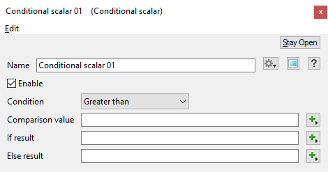
- Condition: This popup lets you choose the condition, or type of comparison, the node uses. A list of the comparisons follows, along with a short description. It should be taken as read that if the input value does not meet the comparision conditions, then the Else result will be output. Here are the comparisons available:
- Greater than: If the input value is greater than the comparison value the If result will be output.
- Greater than or equal to: If the input value is greater than or equal to the comparison value the If result will be output.
- Equal to: If the input value is equal to the comparison value the If result will be output.
- Not equal to: If the input value is not equal to the comparison value the If result will be output.
- Less than: If the input value is less than the comparison value the If result will output.
- Less than or equal to: If the input value is less than or equal to the comparison value the If result will be output.
- Boolean AND: If the input value and the comparison value are greater than 0 the If result will be output.
- Boolean OR: If the input value or the comparison value are greater than 0 the If result will be output.
- Comparison value: This is the value which the input value is compared with.
- If result: This is the value that the node outputs if the input value meets the comparison. It corresponds to value 1 in the examples above.
- Else result (optional): This is the value the node outputs if the input value does not meet the comparison. It corresponds to value 2 in the examples above. This value is optional. If you don't supply an Else result value then the input value will be output by the node, if it does not meet the comparison.
Error conditions:
- It is an error for there to be no input value. In that case 0 is output from the node.
- It is an error for there to no Comparison value and/or no If result value. In this case the input value is output from the node.
Fun with Conditional Scalar[edit]
We can use the Conditional scalar node to create a transition between mountainous terrain and some lower elevation foothills.
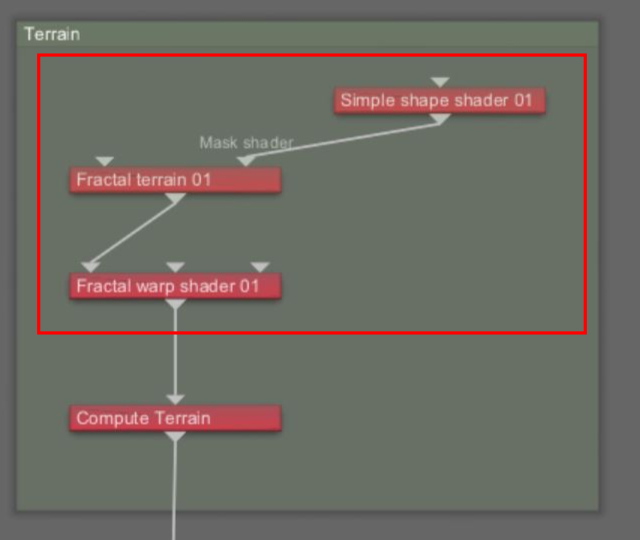
In the default Terragen project, let’s remove any terrain features that currently exist in order to start with a completely smooth and undisplaced planet surface.
- Left-click in the Node Network pane and drag a selection box around the “Simple shape shader”, “Fractal terrain”, and “Fractal warp shader” nodes, then press the “Delete” key on your keyboard to delete them.
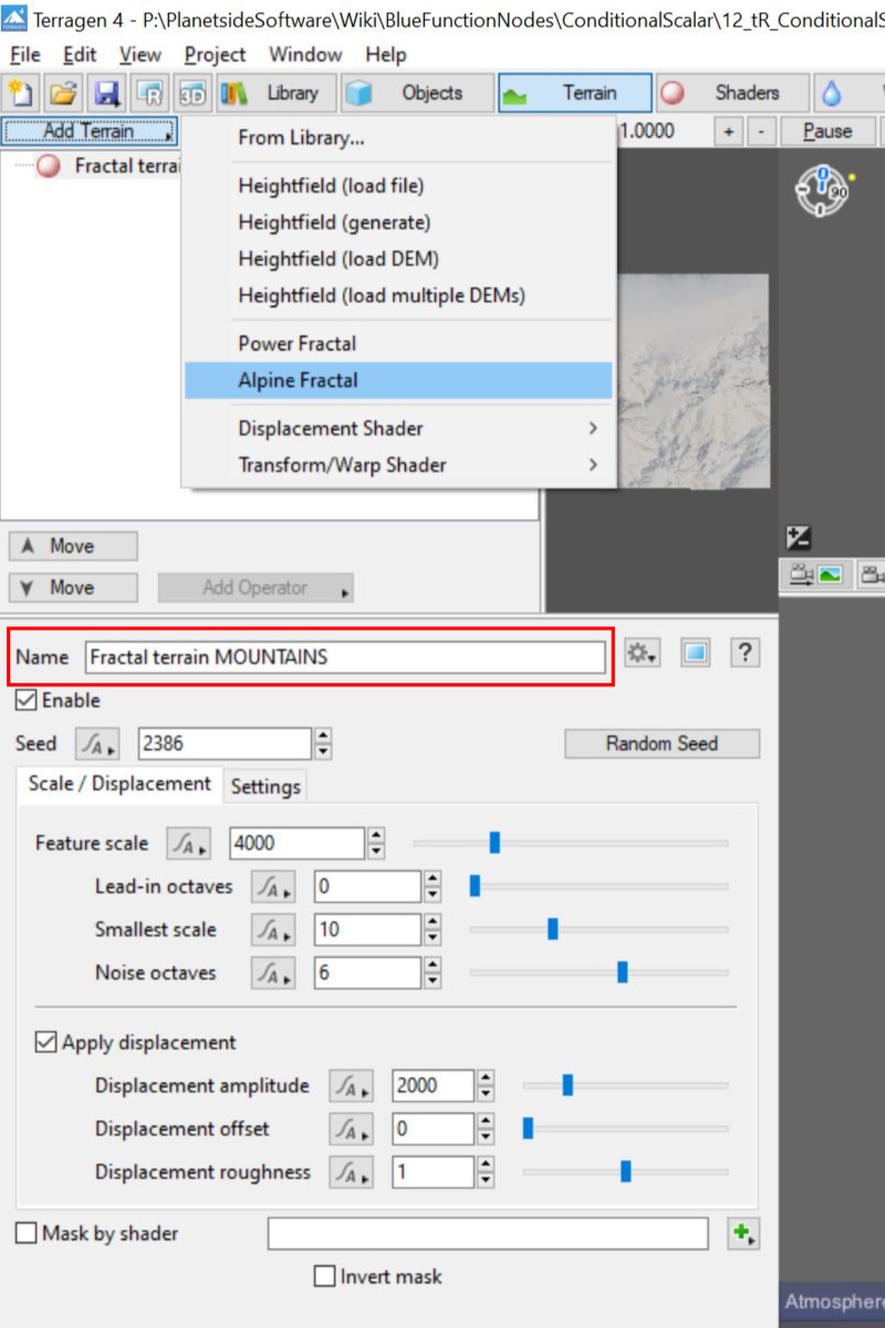
We’ll use an Alpine Fractal terrain for the mountainous area.
- Click the “Terrain” button on the top toolbar.
- Click the “Add Terrain” button at the top of the Terrain Node List.
- Select “Alpine Fractal” from the drop-down list.
- Change the “Name” to something more descriptive, like “Fractal terrain MOUNTAINS”.
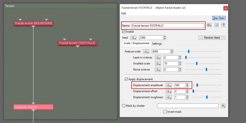
For now, we’ll duplicate the Alpine Fractal terrain node and reduce the height of the mountains to create our foothills.
- In the Node Network pane, click the “Fractal terrain MOUNTAINS” node to select it, then press “Ctrl+D” to duplicate it.
- Double-click the duplicated node to open its dialog window.
- Change the “Name” to something more descriptive, like “Fractal terrain FOOTHILLS”.
- Set the “Displacement amplitude” value to “500”.
We’ll use a Merge shader in order to blend between the two terrain nodes.
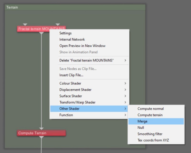
- Right-click on the “Fractal terrain MOUNTAINS” node and select “Other Shader” then “Merge” from the drop down menu, to insert a Merge shader into the workflow.
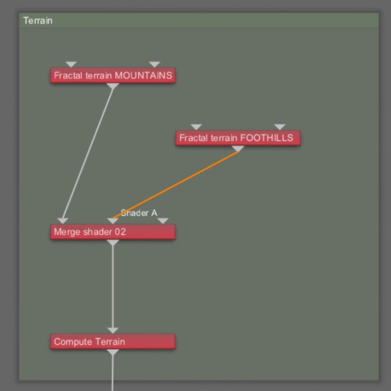
The output from the Fractal terrain MOUNTAIN node was automatically connected to the Main input of the Merge shader in the above step. Now we just need to connect the other terrain node to the Merge shader.
- Drag a connection line from the “Output” of the Fractal terrain FOOTHILLS node to the “Shader A” input of the Merge shader.
The Merge shader controls both the method and how much of the shaders assigned to its inputs are merged together.
The parameters found under the Merge mode tab define the manner in which colour and displacement values are merged. By default the mode is set to Mix (Normal), and for this example we won’t change these settings.
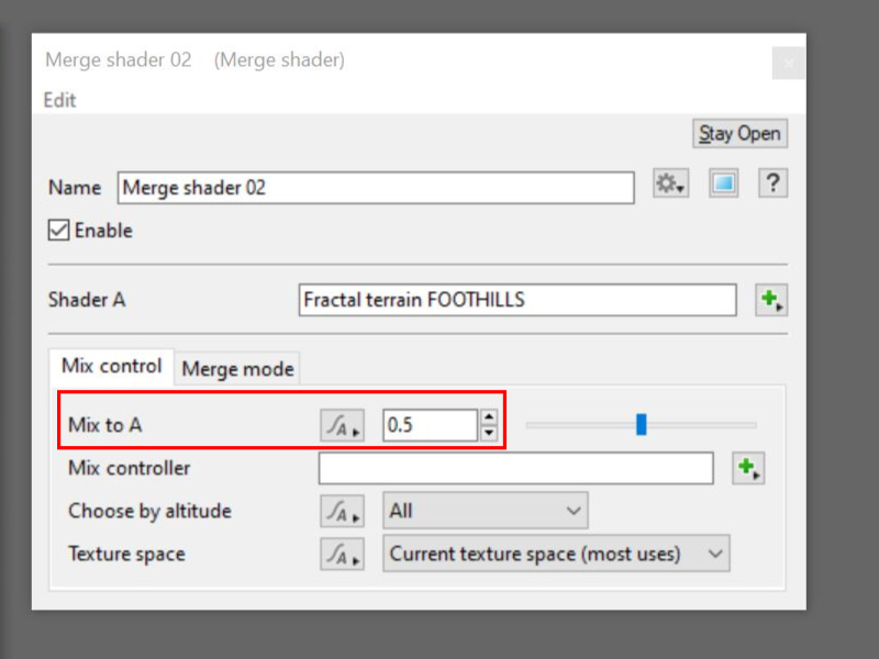
The parameters found under the Mix control tab define how much of the two shaders are merged together. To create our transition area between the mountains and foothills, we’ll focus on the “Mix to A” parameter which controls this amount. With the mode set to Mix (Normal), a “Mix to A” value of “0” results in an output of 100% of the shader assigned to the Main input, while a value of “1” results in an output of 100% of the shader assigned to the Shader A input. A value of “0.5” results in an output of equal amounts of both shaders.
- Double-click on the “Merge” shader to open its dialog window.
- Set the “Mix to A” parameter to values between “0” and “1” to see their effect on the terrain.
| |
Beneath the “Mix to A” setting is the “Mix controller” parameter which accepts a shader or function nodes to control the amount of mixture between the two shaders. This is where we’ll assign the Conditional scalar node.
- Click once in an empty area of the Node Network pane to focus the program’s attention there. A dotted yellow line will become visible around the Node Network pane.
- Press the Tab key or “N” key to open the Quick Node Palette window.
- Start typing the words “Conditional scalar” and the closest match in the Node list will be highlighted.
- With “Conditional scalar” highlighted, press the enter key to add it to the project.
- Drag a connection line from the “Output” of the Conditional scalar node to the ”Mix controller” input of the Merge shader node.
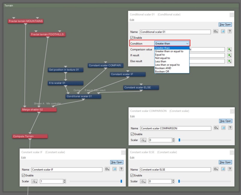
The Conditional scalar node works by performing a comparison and returning a result. The result is conditional on whether the comparison passes or fails the test. So we need to supply the Conditional scalar node with four pieces of information: what we’re testing, what we’re testing for, what to do if the comparison passes the test, and what to do if it fails. Usually other blue function nodes supply this information.
- Using the Quick Node Palette, add a “Get position in texture”, “X to scalar” and three “Constant scalar” nodes.
For our comparison, we’ll use the position of the sample point being rendered on the surface of the planet. The “Get position in texture” node supplies that information to the current render state as vector data. We’ll only test the “X” axis position, so to extract that bit of information we’ll use the “X to scalar” node.
- Drag a connection line from the “Output” of the Get position in texture to the “Main input” of the X to scalar node.
- Drag a connection line from the “Output” of the X to scalar node to the “Main input” of the Conditional scalar node.
We’ll use one of the Constant scalar nodes to supply the comparison value. This is the point at which we want our transition to begin, and for this example we’ll start the transition at the origin, or “0” along the X axis.
- Double-click on one of the “Constant scalar” nodes to open its dialog window.
- Change the “Name” to something descriptive like “Constant scalar COMPARISON”.
- Set the “Scalar” value to “0”.
- Drag the “Output” of the Constant scalar node to the “Comparison value” input of the Conditional scalar node.
We’ll use the two remaining Constant scalar nodes to provide the results of the comparison. One if the comparison passes and the other if it fails.
- Double-click on one of the “Constant scalar” nodes to open its dialog window.
- Change the “Name” to something descriptive like “Constant scalar IF”.
- Set the “Scalar” value to “1”.
- Drag a connection line from the “Output” of the Constant scalar node to the “If result” input of the Conditional scalar node.
- Double-click on the last “'Constant scalar” node to open its dialog window.
- Change the “Name” to something descriptive like “Constant scalar ELSE”.
- Set the “Scalar” value to “0”.
- Drag a connection line from the “Output” of the Constant scalar node to the “Else result” input of the Conditional scalar node.
This completes the setup to allow the Constant scalar node to perform its test. To perform the actual test, we choose a “Condition” from a drop-down menu within the Conditional scalar node.
- Double-click on the “Conditional scalar” node to open its dialog window.
- Set the “Condition” parameter to “Greater than”.
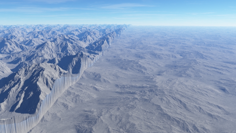
Here is a rendered image of the result. Along the negative X axis, the terrain is that of the mountainous region because its position along the X axis is not greater than the comparison value, i.e. it’s less than 0. Along the positive X axis the terrain is that of the foothills, because its position along the X axis is greater than the comparison value of 0. Note the distinctly sharp cut-off at the origin, or “0” on the X axis
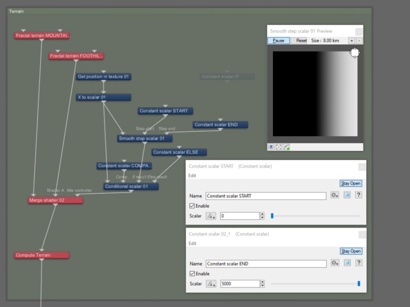
We can see that the Conditional scalar node is working, but we want a soft transition from the mountains to the foothills along the positive X axis. To accomplish this, we’ll make use of a “Smooth step scalar” node, which creates a smooth gradient between the values of 0 and 1 over any length we specify. As the Conditional scalar node evaluates the position along the X axis, instead of returning a value of 1 as soon as the X position exceeds the comparison value of 0, it will return the gradient value from the Smooth step scalar node and result in a smooth transition from the mountains to the foothills.
- Using the Quick Node Palette, add a “Smooth step scalar” node to the project, and two more “Constant scalar" nodes.
- Drag a connection line from the “Output” of the X to scalar node to the “Main input” of the Smooth step scalar node.
- Drag a connection line from the “Output” of the Smooth step scalar node to the “If result” input of the Conditional scalar node.
- Double-click on one of the new Constant scalar nodes to open its dialog window.
- Change its “Name” to something descriptive like “Constant scalar START”.
- Set the “Scalar” value to “0”. This will be the start of the smooth gradient, in metres.
- Drag a connection line from the “Output” of the Constant scalar START node to the “Step start” input of the Smooth step scalar node.
- Double-click on the last Constant scalar node to open its dialog window.
- Change its “Name” to something descriptive like “Constant scalar END”.
- Set the “Scalar” value to “5000”. This will be the end of the smooth gradient, in metres.
- Drag a connection line from the “Output” of the Constant scalar END node to the “Step end” input of the Smooth step scalar node.
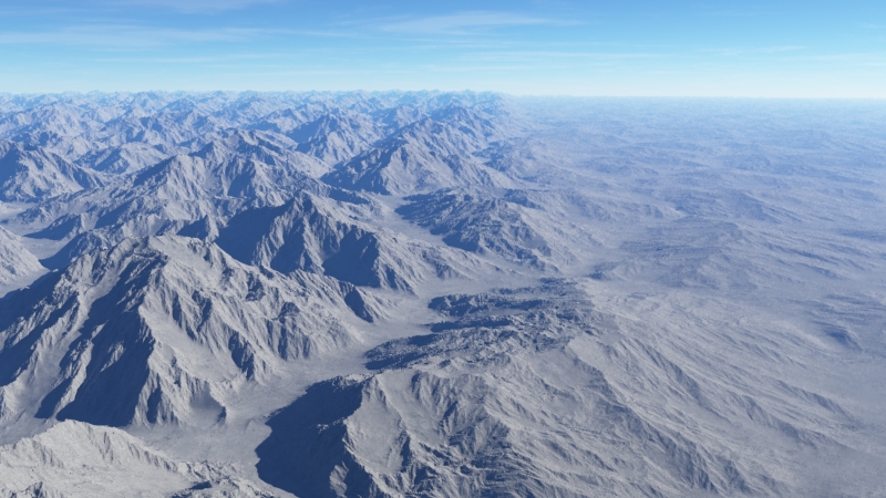
In the rendered image below, we now have a linear and gradual transition from the mountain regions to the foothills over 5,000 metres.
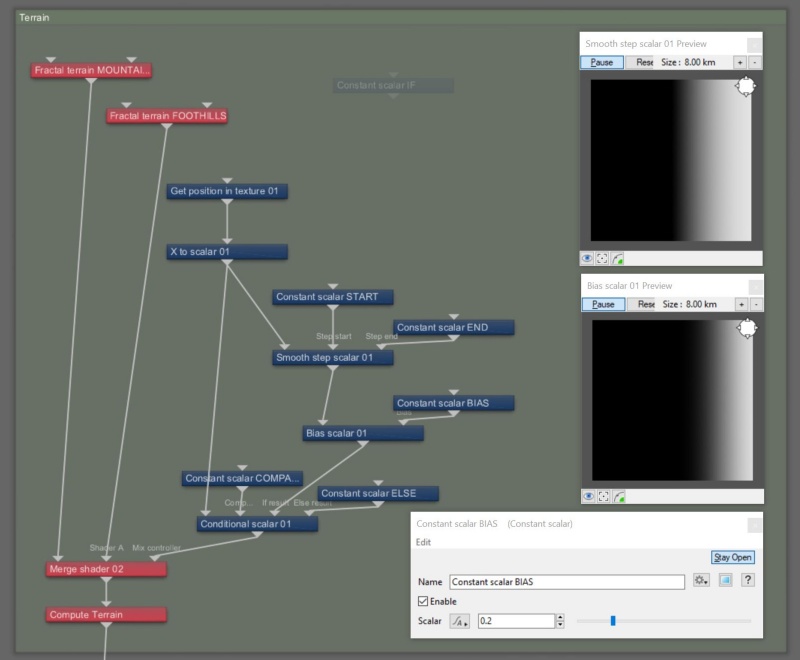
We also have the ability to modify the profile of the gradient, changing it from a perfect linear gradient, to one that favors, or is biased towards, either end of the 0 to 1 range of the gradient. Blue function nodes like “Bias scalar” and “Gain scalar” are useful for this, as is the Colour adjust shader.
- Using the Quick Node Palette, add a “Bias scalar” node and a “Constant scalar” node to the project.
- Drag a connection line from the “Output” of the Smooth step scalar node to the “Main input” of the Bias scalar node.
- Drag a connection line from the “Output” of the Bias scalar node to the “If result” input of the Conditional scalar node.
- Double-click on the new Constant scalar node to open its dialog window.
- Change its “Name” to something descriptive like “Constant scalar BIAS”.
- Set the “Scalar” value to “0.2”. Recommend values for the Bias scalar node are 0.2 - 0.8.
- Drag a connection line from the “Output” of the Constant scalar BIAS node to the “Bias” input of the Bias scalar node.
Now, repeat the last steps using the “Gain scalar” function node instead of the Bias scalar node.
A scalar is a single number. 1, 200.45, -45, -0.2 are all examples of scalar values.
A single object or device in the node network which generates or modifies data and may accept input data or create output data or both, depending on its function. Nodes usually have their own settings which control the data they create or how they modify data passing through them. Nodes are connected together in a network to perform work in a network-based user interface. In Terragen 2 nodes are connected together to describe a scene.
A shader is a program or set of instructions used in 3D computer graphics to determine the final surface properties of an object or image. This can include arbitrarily complex descriptions of light absorption and diffusion, texture mapping, reflection and refraction, shadowing, surface displacement and post-processing effects. In Terragen 2 shaders are used to construct and modify almost every element of a scene.
In a graphical user interface (GUI) on a computer a toolbar is a row, column, or block of onscreen buttons or icons that, when clicked, activate certain functions of the program.
Literally, to change the position of something. In graphics terminology to displace a surface is to modify its geometric (3D) structure using reference data of some kind. For example, a grayscale image might be taken as input, with black areas indicating no displacement of the surface, and white indicating maximum displacement. In Terragen 2 displacement is used to create all terrain by taking heightfield or procedural data as input and using it to displace the normally flat sphere of the planet.
A parameter is an individual setting in a node parameter view which controls some aspect of the node.
A sample refers to a value or set of values at a point in time and/or space. The defining point of a sample is that it is a chosen value out of a continuous signal. In Terragen 2 it is usually a mathematical (procedural) function that is being sampled.
A vector is a set of three scalars, normally representing X, Y and Z coordinates. It also commonly represents rotation, where the values are pitch, heading and bank.
