Tutorial 1: Creating Your First Scene
Contents
Introduction[edit]
Welcome to Terragen! This guide will walk you through creating and rendering your first scene. It will give you a good grounding in many of the basic tools you will use when creating most scenes in Terragen.
Although you can build your scene in any order you choose, this tutorial will guide you through the most typical workflow scenario, which includes:
- The basics of navigating around your scene
- Making some modifications to the terrain
- Using shaders to give the terrain the appearance of dirt, grass, and snow
- Adjusting the lighting
- Working with the sky and clouds
- Creating a high-quality final rendering
For this basic overview, techniques and controls such as camera movement will be introduced once when first needed, after which the operation will be referenced without repeating the instruction. If you need further information about any specific function or feature, refer to the appropriate wiki article for more comprehensive instructions.
[edit]
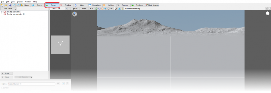
When you start Terragen, it takes you to the terrain layout by default.
Layouts in Terragen can be thought of as tabs that contain different sets of tools for working on different aspects of your scene. The terrain layout is used to manipulate the topography of your Terragen scene.
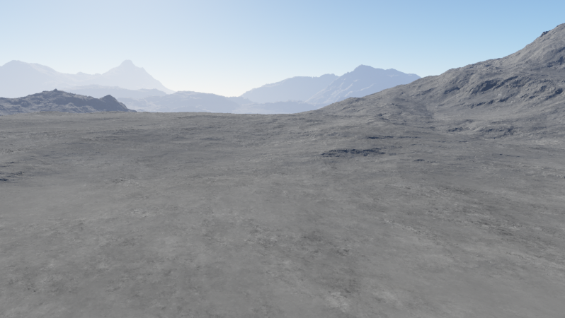
When you start in the terrain layout, you’ll see that Terragen already has default terrain generated. You have a flat, open plane leading into some mountains.
You’re probably curious what this scene looks like outside the current field of view, so let’s move the camera a bit. (Note that this section of the tutorial will assume you have a 3-button mouse, and are using the default controls. Please refer to the Mouse and Key Settings under the Help menu for other options.) You control the camera in the top pane, which is referred to as the 3D Preview pane.
Hold down the Alt key, left-click, and drag upward in the 3D preview to angle the camera up a bit. Now, still holding Alt, middle-click and drag down to move the camera forward. Finally, right-click and drag up to move the camera down into the terrain. You want to get closer to the ground, but make sure you are still well above it. (Note that the camera will pass freely through the terrain, so if you move it down too far, you’ll go through the ground. If this happens, you'll see a red icon appear below the compass in the 3D Preview pane.) Fine-tune your view using these controls to find a perspective you like.
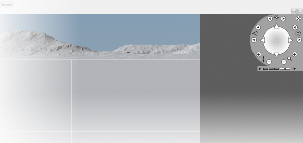
You can also adjust the camera with the navigation control tool located in the upper-right corner of the 3D Preview pane.
When you click this icon, the tool will expand to show a variety of control options.
Some of these controls may be familiar to you if you have experience with other 3D applications. The controls are as follows:
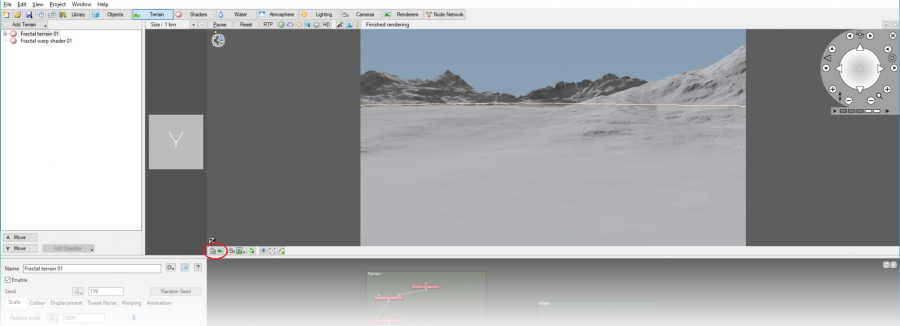
Once you have set the camera to a position you like, click the "Copy this view to the current render camera" button on the bottom-left of the 3D preview toolbar to set the camera position to this view. (If you don’t press this button, the scene will render from the original camera position.)
Now that you’ve updated the render camera, click the Open Render View button in the top toolbar to open the render view. You can also press F3 to open the render view.
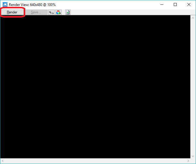
The render view will open, showing a blank, black screen. Click the Render button in the top left to render the scene.
Congratulations, your first scene is now rendering! This process may take a minute. You can watch as the rendering progresses.
Once your render is complete, you might want to save it for posterity. Click the Save button to open the save dialog and save the image.
Some Key Terragen Concepts[edit]
Before we move on to modifying the terrain, let’s briefly touch on a couple of Terragen concepts that will be key to understanding the rest of this tutorial.
An Introduction to Nodes[edit]
You may already be familiar with node-based interfaces from other programs. If so, feel free to skip to the next section. If not, read on! (And don’t worry, it’s not too complicated.)
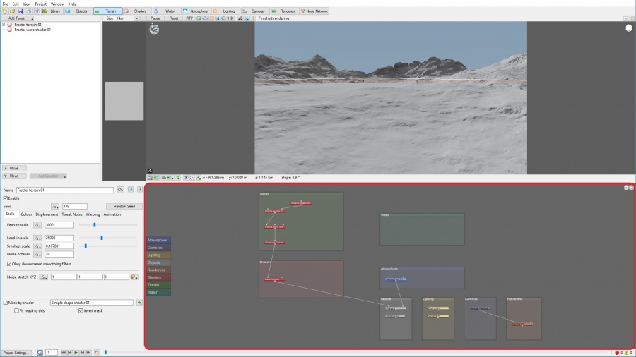
Nodes are the building blocks of a Terragen scene. They can be objects, terrains, shader layers, light sources, etc. You can see them all laid out in the Node Network pane.
Nodes are organized into groups that correspond to Terragen’s layouts. You can see that this default scene starts out with quite a few nodes already in place. It may look like a lot, but don’t worry; we’ll only need to modify a few of them in this tutorial.
The Four Main Panes in a Terragen Layout[edit]
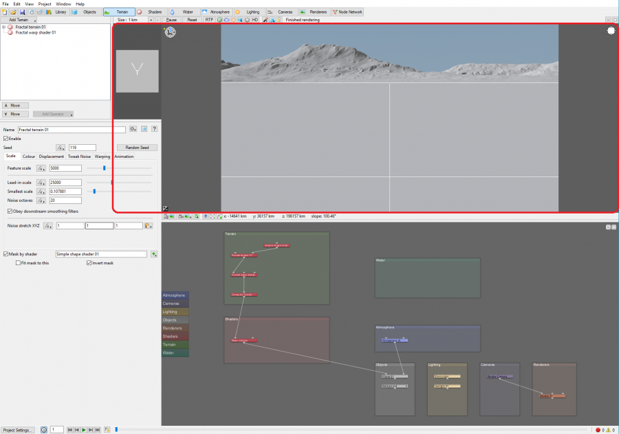
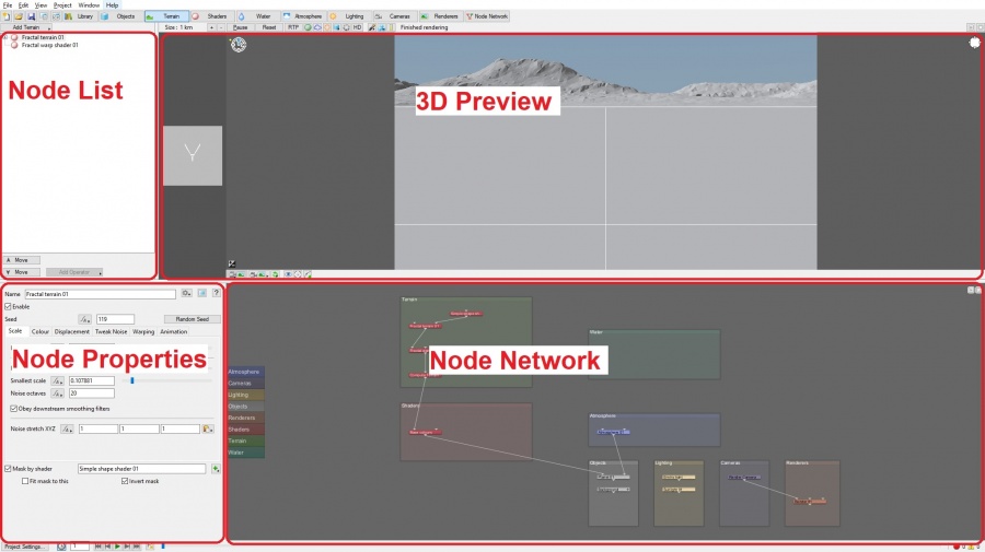
Each layout in Terragen is divided into four main panes that we’ll be referring to throughout this tutorial:
The panes are as follows:
- 3D Preview Pane: You should already have some familiarity with this from the previous section. This is where you’ll navigate around the terrain, change your camera angle, and see a preview of what your scene will look like.
- Node Network Pane: There isn’t much to add here to what we discussed in the “A Brief Introduction to Nodes” section. This displays a list of all the nodes that are being used to build your scene. You won’t be directly interacting with this pane in this tutorial, but it’s good to be aware of it.
- Node List Pane: This shows a list of all the nodes that are grouped with the current layout. This is where you’ll be selecting which nodes to modify.
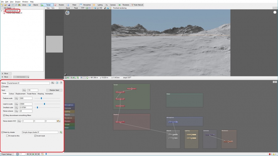
- Node Properties Pane: This shows the properties of whichever node is currently selected in the node list. This is where you’ll be doing most of your work in this tutorial: modifying nodes to make changes to your scene.
Modifying the Terrain[edit]
The default landscape is pretty good, but let’s make it a little more dramatic. Modifying terrain is something you’ll be doing often in Terragen, so it’s good to get exposure to a couple of the options now.
Modifying the Fractal Terrain 01 Node[edit]
To make changes to the terrain, we’ll be modifying the "Fractal terrain 01" node. This node should be selected by default, so its properties should be displayed in the Node Properties pane. If it is not selected, click its name in the node list.
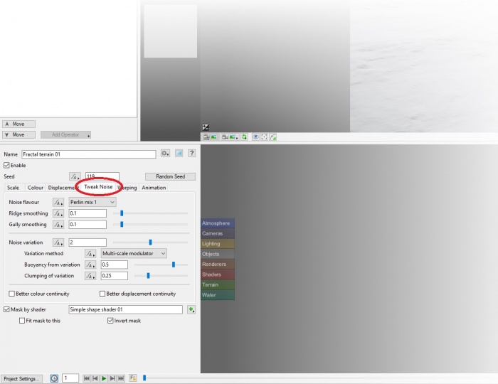
To start, let's make these mountains a bit more sharp-featured and dramatic. In the Node Properties pane, select the Tweak Noise tab.
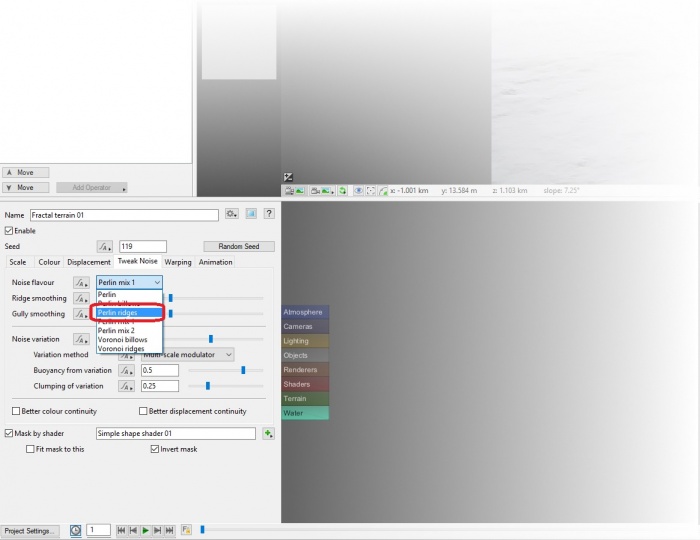
In the "Noise flavour" dropdown, select "Perlin ridges".
This should give you sharper mountain shapes with more dramatic ridges. You might want to do a render of the scene to check out the full effect. You can either open the render window and click Render as you did in the previous section, or press Ctrl+R/Cmd+R to open the render window and begin rendering immediately.
| Note: Do not adjust any settings while Terragen is rendering. Doing so may cause Terragen to crash. |
| Note: When you render the scene, you may notice that it doesn’t look quite as sharp and detailed as you expect. This is because the default render settings aim for a balance between speed and quality. The final section of this tutorial will walk you through creating a high-quality render. |
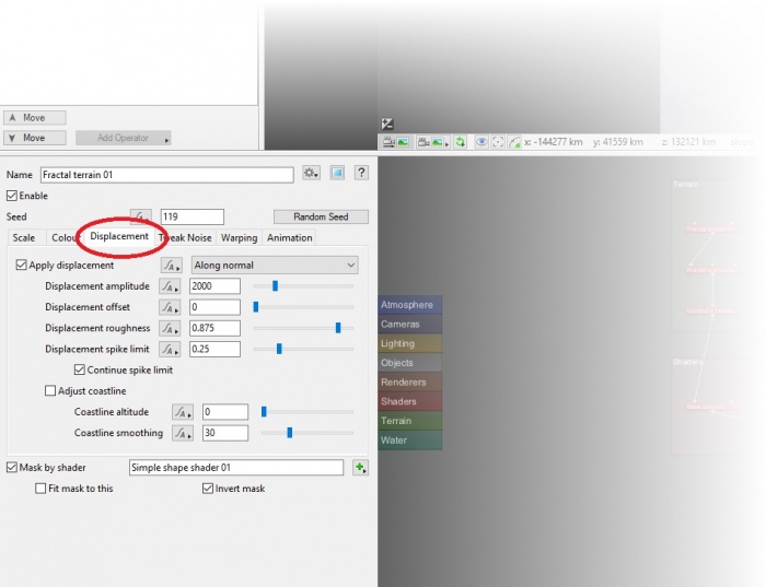
Now let’s make our mountains taller. Select the Displacement tab.
The "Displacement amplitude" is the number affecting the height of our mountains. It’s in meters, which are the default unit in Terragen. However, this number is a little more complicated than just the height of the mountains. It’s actually applied in both the positive (up) and negative (down) direction, so with a value of 2000 we have hills and mountains going up to 1000 meters above the surface of the terrain, and valleys and canyons sinking 1000 meters below the surface of the terrain. So instead of increasing the displacement amplitude, let’s move the starting point for our displacement higher. This is done with the "Displacement offset" value. Set the ‘Displacement offset’ to 1000. This will make all of the displacement happen above the surface level. The mountains should double in height, now going up to 2000 meters. There will no longer be any valleys or canyons that reach below the planet’s surface, but that’s fine for the purposes of this tutorial; there will still be plenty of canyons and valleys between these towering mountains.
You should now find your landscape to be radically transformed, with much larger features. You’ll probably find that you need to adjust your camera quite a bit to get a good view of them, so let’s find a camera angle that will give us a good view for the rest of this tutorial. You'll want to find a vantage point on or near a mountain or other high point of terrain, so that you can see a full range of altitudes for texturing. Look for a mountain with a valley or other depression below it, and a good long view of the terrain into the distance. You can choose whether you want to be close to the terrain, or simply raise your camera higher above the landscape to achieve this vantage point. Once you have found your desired camera position, be sure to click the "Copy this view to the current render camera" button.
As you can see, there are a lot of other ways to adjust the terrain, but we won’t worry about them in this tutorial. Let’s move on to the next section.
| Note: Save your work often! Terragen doesn't auto-save, so be sure to periodically save your progress. (Open the File menu and select either Save or Save As... to save the project.) |
Shaders (Texturing)[edit]
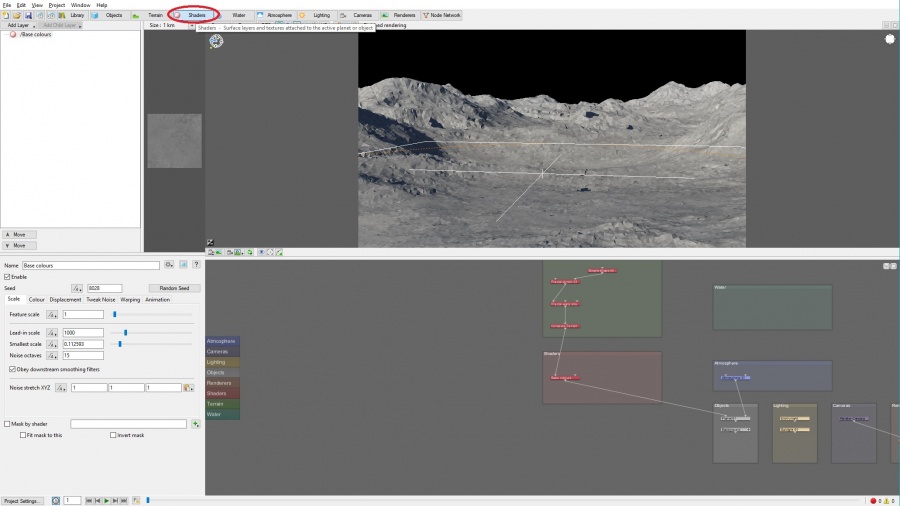
Now that we’re happy with our terrain, let’s give it some more interesting color and texture. Click the Shaders layout button to navigate to the Shaders layout.
This layout is where you’ll find Terragen’s texturing functions. In Terragen, texturing (or surface mapping) is accomplished using "shaders." Like any other building blocks of a Terragen scene, these shaders are added as nodes. These shader nodes create features in your scene such as surface texture and color.
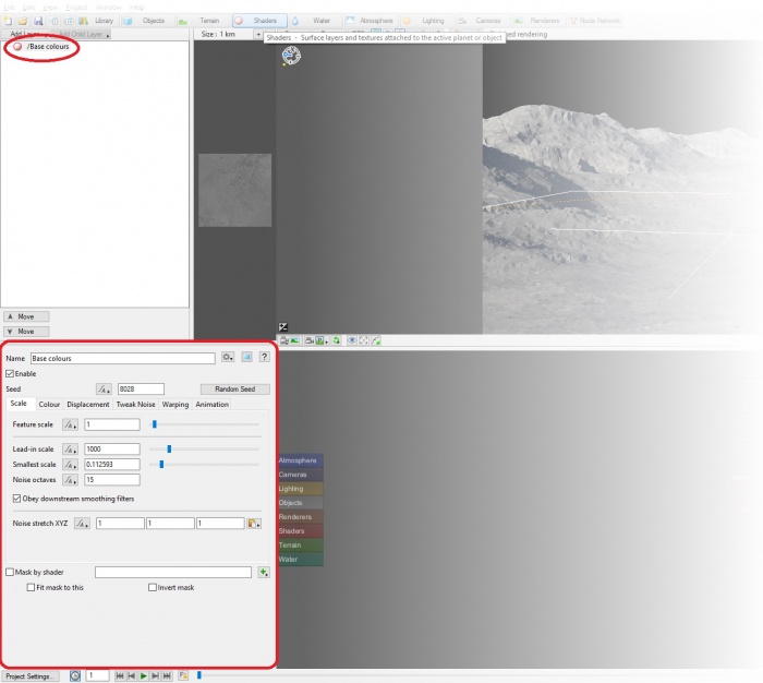
Notice that the scene currently has a single shader node named "Base colours". This node creates the base-level colors for your scene.
| Note: If you're familiar with Terragen Classic, this is similar to the “Surface Map” default layer, which was the basis for the Terragen Classic surface map tree. However, unlike the base layer in Terragen Classic, the "Base colours" node has somewhat different settings from a typical surface layer. |
Adjusting the Colors of the Base Layer[edit]
The "Base colours" node should be selected and showing in the Node Properties pane by default. If it isn’t, select it from the node list.
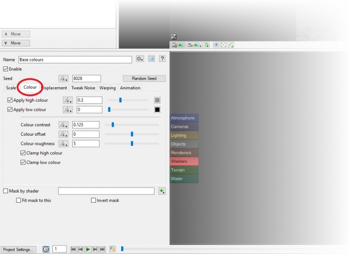
The main thing we want to do with this node is adjust the color, so click the Colour tab.
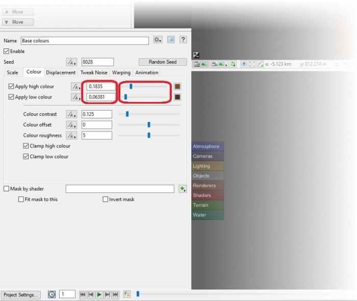
We want to focus on the top section of this tab, which shows the high colour and low colour. The terms "high colour" and "low colour" may be a bit confusing at first; these names don’t correspond to the high and low points of the terrain, but rather to the high and low parts of the internal noise function that is used to apply these colors to the terrain. In simplified terms, this noise function generates color patterns in the range between the high and low colour. Most commonly, you would choose a brighter color for the high colour, and a darker shade of a similar color for the low colour. That’s what we’re going to do now.
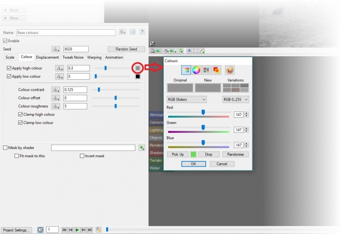
We want to make our base layer look like dirt, so we’re going to choose two shades of brown. Let’s start with the high colour. Click the current colour box on the "Apply high colour" line to open the color picker window for the high colour.
Pick a nice bright earth tone brown for the high colour. (If you’re looking for a good starting point, try RGB 99, 84, 47.) Click "OK" when you have a color that you’re happy with. You will see the preview update with your new color choice.
Now click the current colour box on the "Apply low colour" line to open the color picker window for the low colour. You want a darker shade of brown for the low colour. (Try RGB 47, 43, 32 if you’re looking for a starting point.)
Note that if you just want to adjust the brightness of either color, you can use the sliders to the left of the current colour boxes, or enter a numerical value to the left of the slider.
Adding Grass[edit]
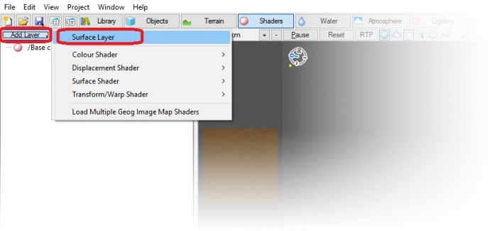
Now that we have dirt, let’s add some grass. We’ll add the grass as another layer. Click the Add Layer button at the top of the node list and select Surface Layer from the drop-down menu.
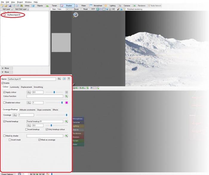
Surface layers default to having full coverage and a middle-grey colour, so your terrain will immediately turn completely grey. The newly-added surface layer should be automatically selected in the node list, but if it isn’t, click "Surface layer 01" from the node list to select it.
First off, click the Name field and change this to something descriptive, like "Grass". This will make it easy to keep track of our layers when we add more. Next we’ll adjust the color. The color settings here work the same as they do in the "Base colours" node except that there is only one color. Click the current colour box on the "Apply colour" line to choose a new color. Pick something greenish-yellow with low-medium saturation. (RGB 102, 119, 27 is a good color to start with.)
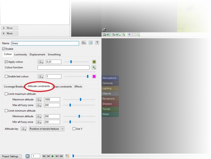
The color is looking good, but we don’t want grass to cover the whole scene. Select the "Altitude constraints" tab.
This tab allows you to constrain this layer to a specific height range with the "Limit maximum altitude" and "Limit minimum altitude" properties. These values are in meters. For the grass, we’re only going to worry about the maximum altitude. To start, check the "Limit maximum altitude" box to enable this property. You should now see the brown tops of the mountains poking out above the grass. The "Maximum altitude" might be fine at 1000, or you might want to tweak it a bit (though these are tall mountains, so at anything below 800 your grass layer might be hard to spot in the mountains). The "Max altitude fuzzy zone" is pretty good at its default value of 200, so let’s leave that as-is for now. (If you want to play with it, this value defines the altitude range that is used to transition between where the layer is fully visible and where it disappears completely at the maximum altitude. Think of it like a gradient tool. So with a maximum altitude of 900 and a fuzzy zone of 200, the altitude range between 700-900 is used to “fade out” the grass layer and show the layer beneath.)
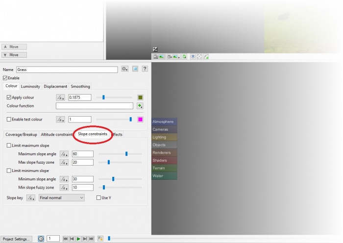
You should now have mountains with grass growing up their slopes, but the line where the grass ends probably looks unrealistically uniform. We’ll fix that in our next step. Select the "Slope constraints" tab.
Enable "Limit maximum slope". This will limit the maximum slope angle (in degrees) that this layer will be applied to. Set the "Maximum slope angle" to about 25 with the "Max slope fuzzy zone" (also in degrees) at about 10. You may wish to test your settings in an actual render (Ctrl+R/Cmd+R).
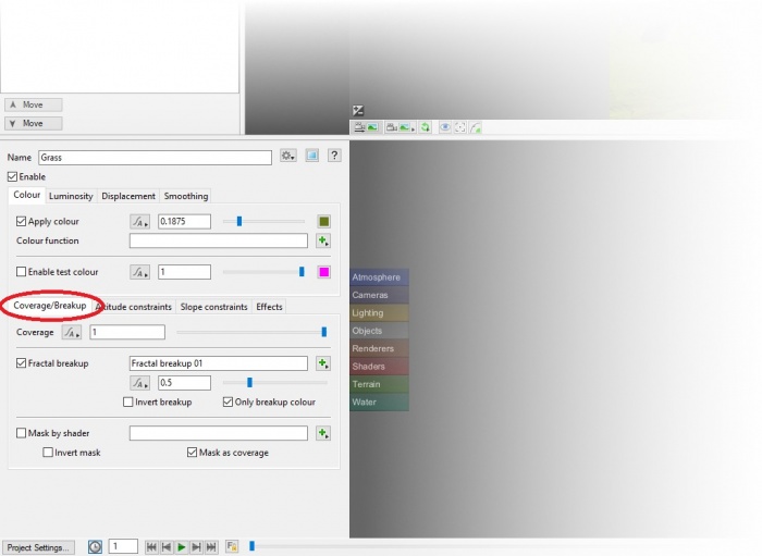
The grass layer is starting to look more natural now, but it still looks a bit too uniform. We’ll address this in the Coverage/Breakup tab. Select this tab to view the options.
There are two settings we’ll be changing here: Coverage and "Fractal breakup". Coverage controls how thoroughly the layer will cover the areas where it appears. Think of it like changing the transparency of the layer, where 1 represents 100% (total coverage), and 0 represents 0% (the layer isn’t visible). Let’s dial the coverage back a bit, with a value of 0.7 for Coverage (i.e. 70% coverage).
"Fractal breakup" breaks up the surface with an appearance of randomness to its texture. Values between 0 and 1 will tend to produce fairly natural results, with 0 being equivalent to turning off the effect entirely and 1 being a smooth distribution. (Values above 1 will make the effect sharper, which can be the right look for some layers, but not for our grass layer.) Set the "Fractal breakup" to 1.0, which should look right for grass.
| Note: If you’re familiar with Terragen Classic, "fractal breakup" works similarly to "fractal noise". |
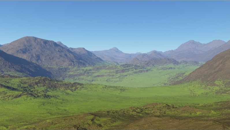
Do a render of the current scene to get an idea of how different it now looks.
Adding Snow[edit]
Let’s add another surface layer and try to make it look like snow. Imagine how you would use the controls you have learned to make a snow layer. If you’re looking for a place to start, try the following settings (and don’t forget to start by renaming the layer to something appropriate!):
- Colour tab:
- Select the color RGB 196, 196, 196.
- Altitude constraints tab:
- Limit the minimum altitude. Try a minimum altitude of 1000, and a fuzzy zone of 350.
- Slope constraints tab:
- Limit the maximum slope with a maximum slope angle of 80, fuzzy zone of 30.
- Coverage/Breakup tab:
- Coverage 0.8, fractal breakup 0.38.
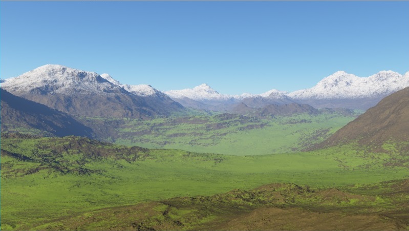
When you are satisfied with your snow, do another render and look at how far your scene has come already!
Lighting and Atmosphere[edit]
The ground is looking pretty good, but what about the sky? Terragen provides a rich suite of tools for adjusting the lighting and atmosphere of your scene, and a variety of options for adding realistic clouds. In this section, we’ll start by changing the angle of the sun, then make some minor adjustments to the default atmosphere, and finally add some high-level clouds.
Adjusting the Light[edit]
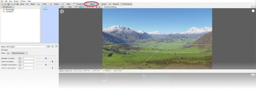
Our first step is to adjust the light so we can test any atmosphere and cloud changes in the proper lighting environment. Although Terragen’s lighting functionality is robust and versatile, our needs for this basic scene are quite simple: we just want to adjust the lighting so that it highlights our terrain nicely. Click the Lighting layout button to navigate to the Lighting layout.
The default scene has two light sources: "Enviro light" and "Sunlight 01". "Sunlight 01" is our direct light source, simulating the sun. "Enviro light" provides global illumination, simulating light which is reflected and scattered by the environment. Together, these light sources provide realistic, natural, Earth-like light, which is exactly what we want for our scene.
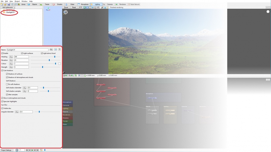
Let’s adjust the sun position and angle to achieve a more dramatic effect. Click the "Sunlight 01" light source in the upper-left pane to bring up its settings.
The position of this light source is controlled by the Heading and Elevation settings. These settings are relative to the coordinate origin and they are both measured in degrees—360 degrees for the Heading, and 90 to -90 degrees for Elevation. A setting of 90 for Elevation corresponds to a light source directly overhead, while -90 is directly below (and thus generally out of sight).
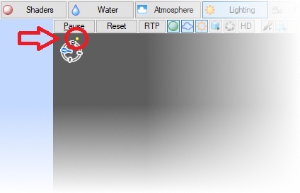
The lighting that works best for your particular terrain and camera angle will vary greatly. Try adjusting the Heading until you get an angle that’s in front of the camera just off to the left or right. Note that the position of the sun is shown in the compass in the top left corner of the 3D Preview pane.
Keep adjusting the Heading until you have an angle that’s in front of the camera and that you feel brings out the best in your scene.
Now we’re going to reduce the Elevation to anything between 8 and 6. This will put the sun at the beginning of sunset (10-0 degrees is sunset.) You’ll note that the shadows get longer and more dramatic (as expected), but the light changes as well. This is because Terragen simulates the way that the color of the light gets warmer as the angle of the sun gets low. (You can change it to something really low, like 2, if you want to see this effect more dramatically. Just change it back to 6-8 when you’re done so that you still get a decent amount of light shining down between the mountains.)
You may want to do a render to make sure you’re happy with the sun’s position.
That’s all the lighting adjustment we’ll need to do for this tutorial. Next we’ll adjust the atmosphere.
Adjusting the Atmosphere[edit]
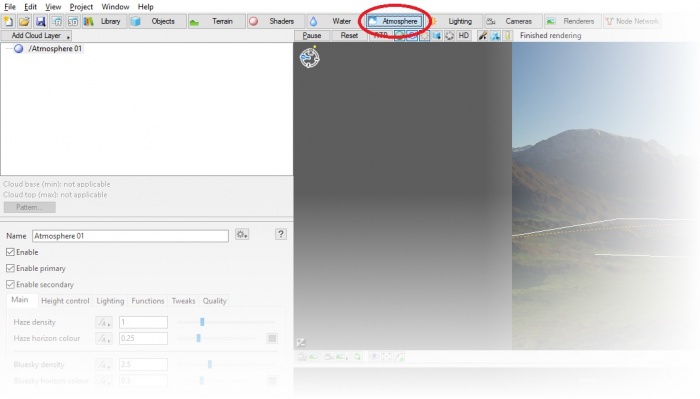
The atmosphere settings in Terragen allow you to adjust things such as haze and sky color. Click the Atmosphere layout button to navigate to the atmosphere layout.
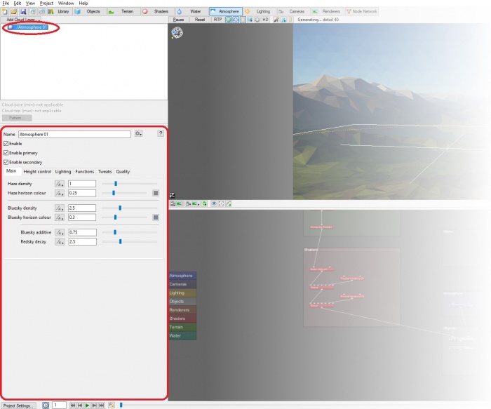
In the atmosphere layout, you’ll see a single node named "Atmosphere 01". It should be selected by default. If it isn’t, click it to bring up its settings.
The Main tab in the Atmosphere 01 settings should be selected by default. Most of the settings in this tab are fine at their default, but we want to make the color of our sunset more dramatic. As noted in the previous section, Terragen automatically adjusts the color of the light based on the height of the sun. However, it does this assuming very clear conditions, where the amount of warm color that comes out as the sun sets isn’t too dramatic. We’re going to adjust this by increasing the "Redsky decay" to simulate a dustier atmosphere that brings out more red in the sunset. Play with it a bit and you’ll notice how quickly the color of your scene changes. You’ll also notice that the "Bluesky density", "Bluesky horizon colour", and "Bluesky additive" adjust automatically; these properties are all interdependent, so adjusting one will adjust the others accordingly. Enter a "Redsky decay" value of 4.5 or close to it; this should give a nice orange glow to everything without overpowering the scene.
Adding Clouds[edit]
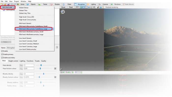
The last thing we’ll add to our scene is some nice clouds to liven up that plain blue sky. Clouds are added in the atmosphere layout, which you should already be in. Click the Add Cloud Layer button above the node list and select Mid-level: Altocumulus Castellanus, Large.
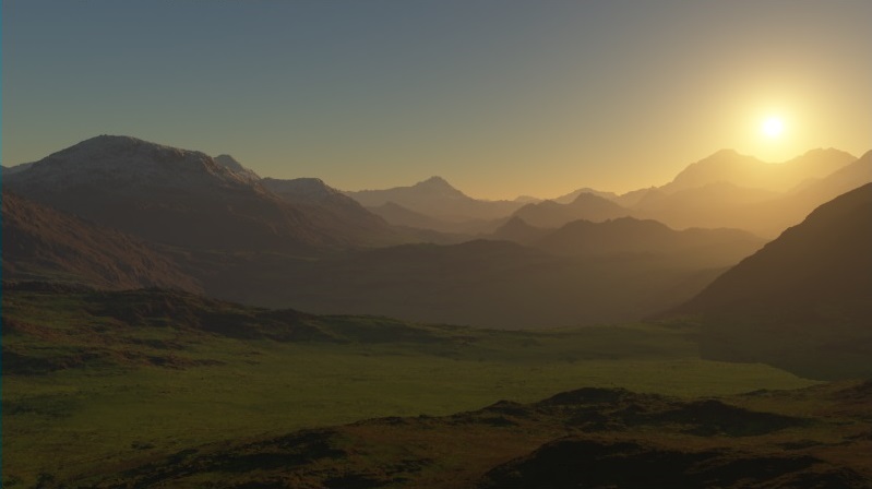
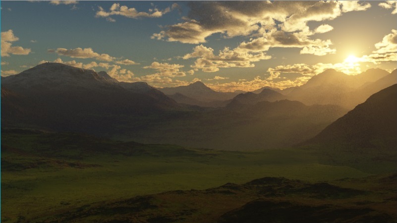
Your sky should immediately be covered in some scattered high altitude three dimensional clouds. Try a render to see how it looks. You should get something like this:
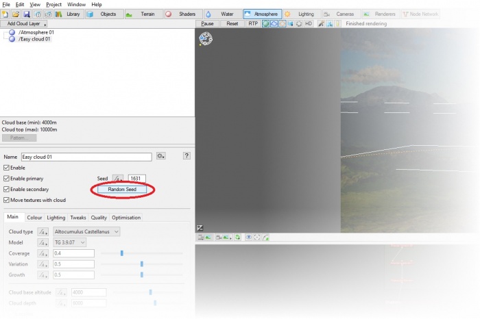
If you don’t like the position of the clouds, there are a number of ways you can tweak them. The simplest thing to do, though, is try another random cloud pattern. Make sure that your cloud layer, "Easy cloud 01", is selected from the node list, then click the Random Seed button in the node options.
Click the button a few times until you find a pleasing distribution of clouds with the sun at least partly uncovered. You may have to wait a moment for the preview to update with enough detail to see clearly. Once you've found a pattern you like, try another render.
Render Nodes and Quality Settings[edit]
As previously noted, your renders up to this point have been a bit grainy and lacking in detail. That’s because the default render settings are intended to balance speed with a reasonable level of quality, rather than the optimal quality you want in a final render. In this section, we’ll take a brief look at the available detail settings to improve the look of our scene and then we’ll render a high quality final image.
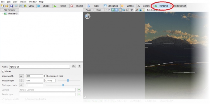
Click the Renderers layout button to navigate to the Renderers layout.
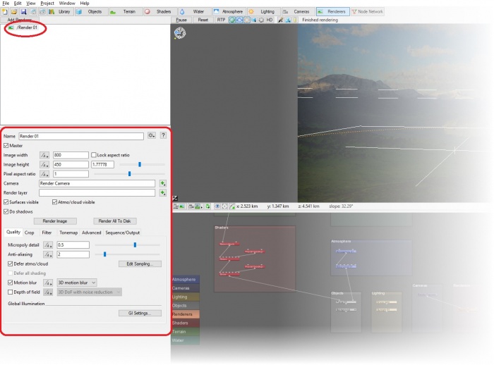
Render nodes define important render-related settings including image resolution, quality, gamma correction, and contrast. You can use multiple render nodes to set up a variety of commonly used render types and settings and quickly switch between them, but for this tutorial we’ll just alter the existing render node, "Render 01". This node should be selected by default with its properties showing in the Node Properties pane. If it is not selected, select it from the node list.
We’ll be tweaking a few properties here to increase the quality of the render. Let’s start with the resolution. Change the "Image width" to 1280 and the "Image height" to 720. This will give us a larger (i.e. higher-resolution) image.
Moving down to the Quality tab (which should be selected by default), we’ll adjust the "Micropoly detail". This setting controls the detail level of the terrain. (It also controls the detail level for water and certain objects, but we don’t have those in this tutorial.) Small adjustments to this value produce significant changes, so let’s just increase the "Micropoly detail" level to 0.65. This should give us a nice level of detail while still allowing the scene to render in a reasonable amount of time.
Finally, let’s increase Anti-aliasing to 4. This should give the render smoother edges.
| Note: If you are familiar with Terragen Classic, you'll see that these quality settings allow for much more control than before. There is no more need for the downsample trick commonly used in that version. |
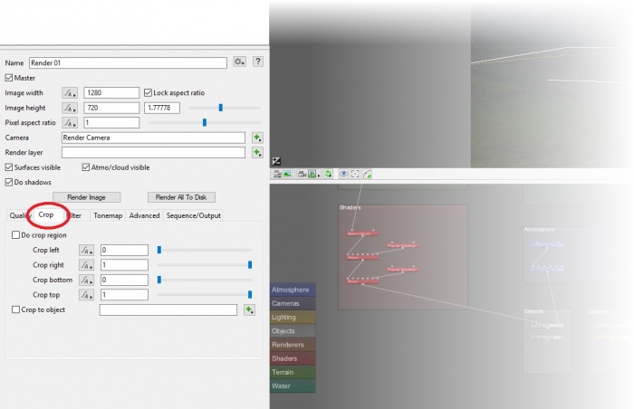
Now we want to test our new quality settings, but don’t want to wait for the whole scene to render. Fortunately, Terragen includes a crop function for just this purpose. You can render just a piece of your scene to get an idea of how the render settings will look. Click the Crop tab in the Node Properties pane.
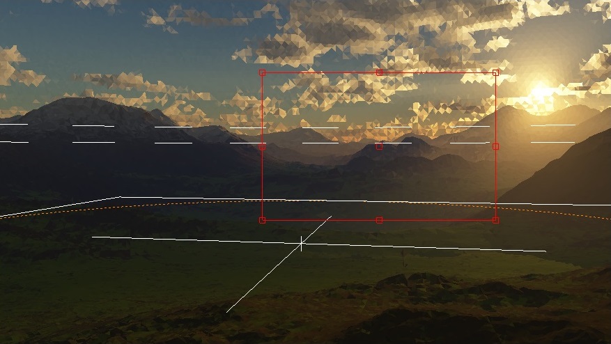
Check the "Do crop region" box to turn the crop function on. You should see a red box appear around the borders of your 3D preview. This red box indicates the boundaries of your crop region.
You can adjust the crop area using the crop sliders, but it's much easier to simply drag the crop area boundaries in the 3D Preview pane. Drag from a corner or middle of an edge to adjust the crop outline. Drag the small square in the middle of the crop outline to move the whole crop outline. Move the crop outline so that it incorporates both land and sky, preferably with some clouds included.
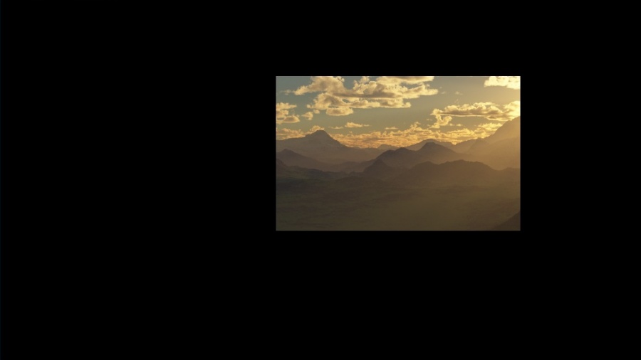
Render a test and see how the new detail settings look in your crop region. You’ll note that even with the cropping, rendering takes quite a bit longer than it did before.
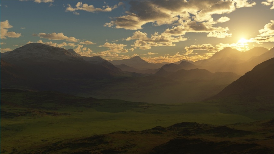
That looks pretty good, so let’s start the final image render. Uncheck "Do crop region" so that the full image will render. Now start the final render. This may take some time, so be patient (or step away from the computer for a bit and come back later).
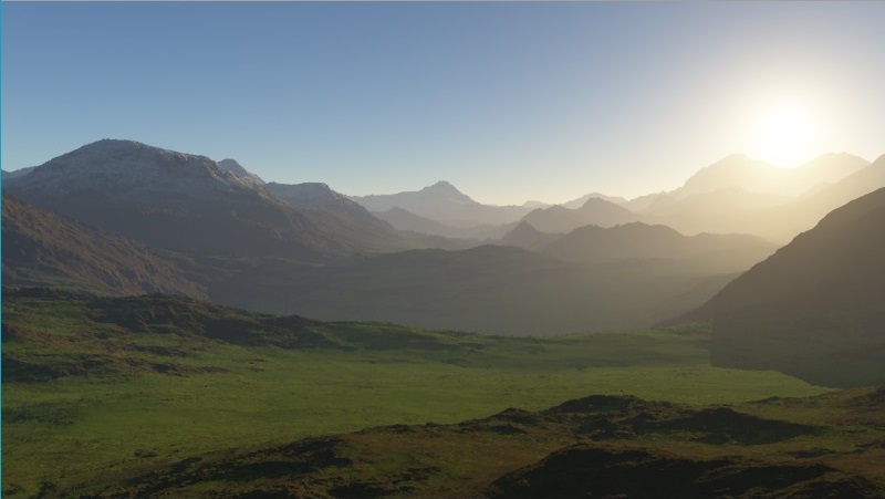
You should end up with something like this.
Congratulations, you’ve just created your first Terragen scene! With the fundamentals under your belt, you’re ready to experiment on your own. Or, if you prefer, read further guides to learn more.
Make sure you save your work, especially if you plan to check out more tutorials. Future tutorials will keep building on this scene, so you'll want to have it handy.
A detailed graphic representation of the surface features of a place or object. The features themselves; terrain.
In a graphical user interface (GUI) on a computer a toolbar is a row, column, or block of onscreen buttons or icons that, when clicked, activate certain functions of the program.
A single object or device in the node network which generates or modifies data and may accept input data or create output data or both, depending on its function. Nodes usually have their own settings which control the data they create or how they modify data passing through them. Nodes are connected together in a network to perform work in a network-based user interface. In Terragen 2 nodes are connected together to describe a scene.
A shader is a program or set of instructions used in 3D computer graphics to determine the final surface properties of an object or image. This can include arbitrarily complex descriptions of light absorption and diffusion, texture mapping, reflection and refraction, shadowing, surface displacement and post-processing effects. In Terragen 2 shaders are used to construct and modify almost every element of a scene.
The Node List is a part of the Terragen interface that shows a list of nodes along the left side of the application window. The Node List generally shows only those nodes that are relevant to the current Layout (e.g. Terrain, Atmosphere). It sometimes includes buttons or other controls that are specific to a particular Layout as well. The Node List is hierarchical and each level is collapsible.
Literally, to change the position of something. In graphics terminology to displace a surface is to modify its geometric (3D) structure using reference data of some kind. For example, a grayscale image might be taken as input, with black areas indicating no displacement of the surface, and white indicating maximum displacement. In Terragen 2 displacement is used to create all terrain by taking heightfield or procedural data as input and using it to displace the normally flat sphere of the planet.
