Difference between revisions of "Heightfield Crop"
(Added descriptions and example images for Heightfield Crop.) |
(Updated descriptions and replaced most example images using Heightfield at Position lower left. Moved Heightfield Position documentation to after Heightfield Crop descriptions & examples.) |
||
| Line 3: | Line 3: | ||
== Overview == | == Overview == | ||
| − | The Heightfield Crop node is used to crop a portion of the heightfield it is applied to. | + | The Heightfield Crop node is used to crop a portion of the heightfield it is applied to. Think of drawing a box by entering coordinates into the “Bottom left” and “Top right” settings. These coordinates correspond to the number of data samples in a TER file, or the number of pixels in an image file, such as an EXR. The coordinates start at the bottom left corner (0,0) of the heightfield, and the top right coordinates should be greater values than the bottom left. In this way you can isolate any section of the heightfield. |
| − | |||
| − | |||
| − | |||
| − | |||
| − | |||
| − | |||
| − | |||
| − | |||
| − | |||
| − | |||
| − | |||
| − | |||
| − | |||
| − | |||
| − | |||
| − | |||
| Line 36: | Line 20: | ||
Here the image has been applied as a heightfield. | Here the image has been applied as a heightfield. | ||
| − | [[File: | + | [[File:HFCrop_00-2_NoCrop.jpg|none|400px|Image used as heightfield, no cropping.]] |
<br /> | <br /> | ||
| Line 43: | Line 27: | ||
* ''' Crop: ''' When checked, or enabled, the heightfield is cropped by the settings below. Note that it is sometimes necessary to disable then re-enable this checkbox after changing the other settings in order to recalculate the crop region correctly. | * ''' Crop: ''' When checked, or enabled, the heightfield is cropped by the settings below. Note that it is sometimes necessary to disable then re-enable this checkbox after changing the other settings in order to recalculate the crop region correctly. | ||
<br /> | <br /> | ||
| − | * '''Bottom left: ''' This is the | + | * '''Bottom left: ''' This setting is the bottom left corner of the cropped section. Coordinates are measured from the bottom left corner (0,0) of the heightfield. |
| + | * '''Top right: ''' This setting is the top right corner of the cropped section. Coordinates are measured from the bottom left corner (0,0) of the heightfield, therefore they should be larger than the “Bottom left” values. | ||
<ul> | <ul> | ||
| − | [[File:HFCrop_09_BottomLeft_0001.jpg|none|800px|Bottom left exampless.]] | + | <!-- [[File:HFCrop_09_BottomLeft_0001.jpg|none|800px|Bottom left exampless.]]--> |
| + | {| | ||
| + | |- | ||
| + | | [[File:HFCrop_12_BotL0x500_TopR500x1000.jpg|none|400px|Bottom left coordinates = 0,500, Top right coordinates = 500,1000 ]] || [[File:HFCrop_13_BotL500x500_TopR1000x1000.jpg|none|400px|Bottom left coordinates = 500,500, Top right coordinates = 1000,1000]] | ||
| + | |- | ||
| + | | [[File:HFCrop_14_BotL0x0_TopR500x500.jpg|none|400px|Bottom left coordinates = 0,0, Top right coordinates = 500,500]] || [[File:HFCrop_15_BotL500x0_TopR1000x500.jpg|none|400px|Bottom left coordinates = 500,0, Top right coordinates = 1000,500]] | ||
| + | |} | ||
</ul> | </ul> | ||
| − | |||
| − | |||
| − | |||
| − | |||
| − | |||
| Line 58: | Line 44: | ||
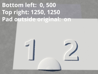
| − | * '''Pad outside original: ''' When unchecked, or disabled, values entered in the “Bottom left” and “Top right” settings that exceed the actual number of data samples in the heightfield are ignored. When checked, or enabled, the cropped region is increased | + | * '''Pad outside original: ''' When unchecked, or disabled, values entered in the “Bottom left” and “Top right” settings that exceed the actual number of data samples in the heightfield are ignored. When checked, or enabled, the cropped region is increased or "padded" by the amount that the data samples represent. |
<ul> | <ul> | ||
| − | [[File: | + | {| |
| + | |- | ||
| + | | [[File:HFCrop_16_PadOutsideOff.jpg|none|400px|Pad outside original disabled.]] || [[File:HFCrop_17_PadOutsideOn.jpg|none|400px|Pad outside original enabled.]] | ||
| + | |} | ||
</ul> | </ul> | ||
</ul> | </ul> | ||
<br /> | <br /> | ||
| + | == Heightfield shader "Position" setting == | ||
| + | Cropped regions are positioned based on the Heightfield’s “Position” settings. This radio button can be found under the Heightfield shader’s Location tab. | ||
| + | |||
| + | |||
| + | [[File:HFShader_GUI_PositionRadioButton.png|none|470px|Heightfield shader Location tab]] | ||
| + | |||
| + | |||
| + | |||
| + | {| | ||
| + | |- | ||
| + | | [[File:HFCrop_18-2_HFPositionCentre.jpg|none|266px|Position centre enabled.]] || [[File:HFCrop_19_HFPositionLowL.jpg|none|266px|Postion lower left enabled.]] || [[File:HFCrop_20_HFPositionUpR.jpg|none|266px|Position upper left enabled.]] | ||
| + | |} | ||
| + | <br /> | ||
[[Category: Heightfield Operators]] | [[Category: Heightfield Operators]] | ||
Latest revision as of 00:49, 6 January 2021
Overview[edit]
The Heightfield Crop node is used to crop a portion of the heightfield it is applied to. Think of drawing a box by entering coordinates into the “Bottom left” and “Top right” settings. These coordinates correspond to the number of data samples in a TER file, or the number of pixels in an image file, such as an EXR. The coordinates start at the bottom left corner (0,0) of the heightfield, and the top right coordinates should be greater values than the bottom left. In this way you can isolate any section of the heightfield.
Settings:
-
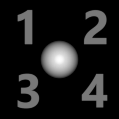
In the example images below this image was used as the heightfield to easily demonstrate where the heightfield is cropped and how it is positioned. The image resolution is 1000 x 1000 pixels, and the values used to crop the heightfield are based on pixels.
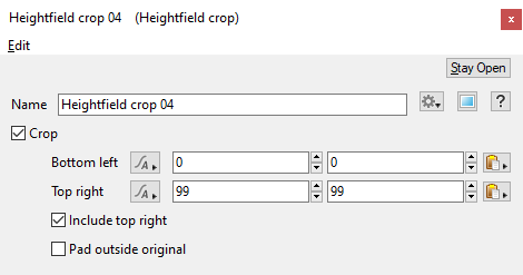
- Name: This setting allows you to apply a descriptive name to the node, which can be helpful when using multiple Heightfield crop nodes in a project.
- Crop: When checked, or enabled, the heightfield is cropped by the settings below. Note that it is sometimes necessary to disable then re-enable this checkbox after changing the other settings in order to recalculate the crop region correctly.
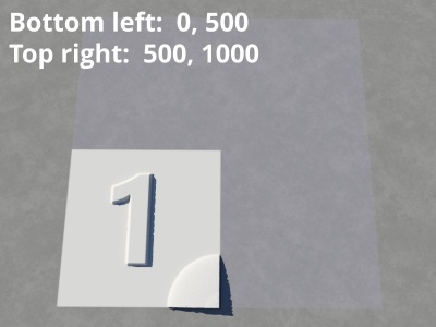
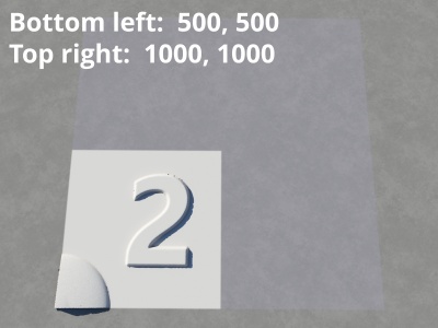
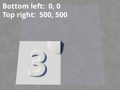
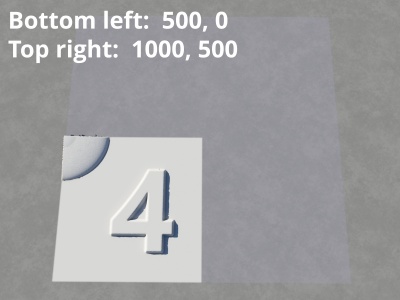
- Bottom left: This setting is the bottom left corner of the cropped section. Coordinates are measured from the bottom left corner (0,0) of the heightfield.
- Top right: This setting is the top right corner of the cropped section. Coordinates are measured from the bottom left corner (0,0) of the heightfield, therefore they should be larger than the “Bottom left” values.
- Include top right:
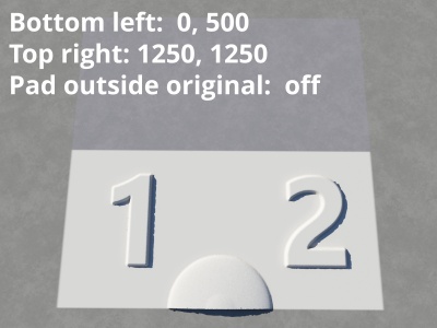
- Pad outside original: When unchecked, or disabled, values entered in the “Bottom left” and “Top right” settings that exceed the actual number of data samples in the heightfield are ignored. When checked, or enabled, the cropped region is increased or "padded" by the amount that the data samples represent.
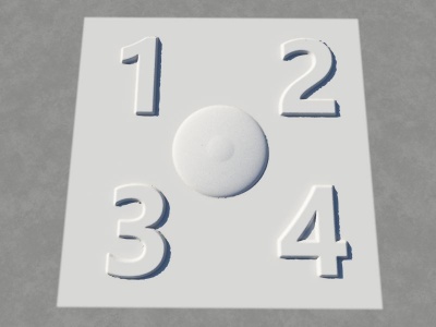
Here the image has been applied as a heightfield.
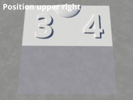
Heightfield shader "Position" setting[edit]
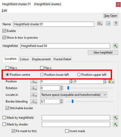
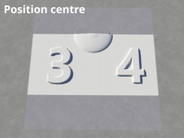
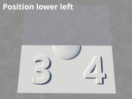
Cropped regions are positioned based on the Heightfield’s “Position” settings. This radio button can be found under the Heightfield shader’s Location tab.
A heightmap or heightfield is an array of height values, usually in a grid which describe the height at specific points in a defined area. Heightfields are used to represent real-world and virtual terrain in a specific, easily converted format. Most heightfields can be represented as simple image data in grayscale, with black being minimum height and white being maximum height.
A single object or device in the node network which generates or modifies data and may accept input data or create output data or both, depending on its function. Nodes usually have their own settings which control the data they create or how they modify data passing through them. Nodes are connected together in a network to perform work in a network-based user interface. In Terragen 2 nodes are connected together to describe a scene.
A shader is a program or set of instructions used in 3D computer graphics to determine the final surface properties of an object or image. This can include arbitrarily complex descriptions of light absorption and diffusion, texture mapping, reflection and refraction, shadowing, surface displacement and post-processing effects. In Terragen 2 shaders are used to construct and modify almost every element of a scene.
